Lincoln Corsair: Automatic Transmission - 8-Speed Automatic Transmission – 8F35/8F40 / Diagnosis and Testing - DTC Chart and Pinpoint Tests - 2.0L EcoBoost (177kW/240PS) – MI4
Diagnostic Trouble Code (DTC) Chart
Diagnostics in this manual assume a certain skill level and knowledge of Ford-specific diagnostic practices.
REFER to: Diagnostic Methods (100-00 General Information, Description and Operation).
| Module | DTC | Description | Action |
|---|---|---|---|
| PCM | P0657:00 | Actuator Supply Voltage 'A' Circuit/Open: No Sub Type Information | GO to Pinpoint Test A |
| PCM | P0657:00 | Actuator Supply Voltage 'A' Circuit/Open: No Sub Type Information | GO to Pinpoint Test F |
| PCM | P0702:00 | Transmission Control System Electrical: No Sub Type Information | GO to Pinpoint Test J |
| PCM | P0706:00 | Transmission Range Sensor 'A' Circuit Range/Performance: No Sub Type Information | GO to Pinpoint Test C |
| PCM | P0707:00 | Transmission Range Sensor 'A' Circuit Low: No Sub Type Information | GO to Pinpoint Test C |
| PCM | P0708:00 | Transmission Range Sensor 'A' Circuit High: No Sub Type Information | GO to Pinpoint Test C |
| PCM | P0709:00 | Transmission Range Sensor 'A' Circuit Intermittent: No Sub Type Information | GO to Pinpoint Test C |
| PCM | P0710:00 | Transmission Fluid Temperature Sensor 'A' Circuit: No Sub Type Information | GO to Pinpoint Test B |
| PCM | P0711:00 | Transmission Fluid Temperature Sensor 'A' Circuit Range/Performance: No Sub Type Information | GO to Pinpoint Test B |
| PCM | P0712:00 | Transmission Fluid Temperature Sensor 'A' Circuit Low: No Sub Type Information | GO to Pinpoint Test B |
| PCM | P0713:00 | Transmission Fluid Temperature Sensor 'A' Circuit High: No Sub Type Information | GO to Pinpoint Test B |
| PCM | P0715:00 | Input/Turbine Shaft Speed Sensor 'A' Circuit: No Sub Type Information | GO to Pinpoint Test D |
| PCM | P0716:00 | Input/Turbine Shaft Speed Sensor 'A' Circuit Range/Performance: No Sub Type Information | GO to Pinpoint Test G |
| PCM | P0717:00 | Input/Turbine Shaft Speed Sensor 'A' Circuit No Signal: No Sub Type Information | GO to Pinpoint Test D |
| PCM | P0718:00 | Input/Turbine Shaft Speed Sensor 'A' Circuit Intermittent: No Sub Type Information | GO to Pinpoint Test D |
| PCM | P0720:00 | Output Shaft Speed Sensor Circuit: No Sub Type Information | GO to Pinpoint Test D |
| PCM | P0721:00 | Output Shaft Speed Sensor Circuit Range/Performance: No Sub Type Information | GO to Pinpoint Test G |
| PCM | P0722:00 | Output Shaft Speed Sensor Circuit No Signal: No Sub Type Information | GO to Pinpoint Test D |
| PCM | P0723:00 | Output Shaft Speed Sensor Circuit Intermittent: No Sub Type Information | GO to Pinpoint Test D |
| PCM | P0729:00 | Gear 6 Incorrect Ratio: No Sub Type Information | GO to Pinpoint Test K |
| PCM | P0731:00 | Gear 1 Incorrect Ratio: No Sub Type Information | GO to Pinpoint Test L |
| PCM | P0732:00 | Gear 2 Incorrect Ratio: No Sub Type Information | GO to Pinpoint Test M |
| PCM | P0733:00 | Gear 3 Incorrect Ratio: No Sub Type Information | GO to Pinpoint Test N |
| PCM | P0734:00 | Gear 4 Incorrect Ratio: No Sub Type Information | GO to Pinpoint Test O |
| PCM | P0735:00 | Gear 5 Incorrect Ratio: No Sub Type Information | GO to Pinpoint Test P |
| PCM | P0736:00 | Reverse Incorrect Ratio: No Sub Type Information | GO to Pinpoint Test S |
| PCM | P073D:00 | Unable to Engage Neutral: No Sub Type Information | GO to Pinpoint Test T |
| PCM | P073E:00 | Unable to Engage Reverse: No Sub Type Information | GO to Pinpoint Test U |
| PCM | P073F:00 | Unable to Engage Gear 1: No Sub Type Information | GO to Pinpoint Test V |
| PCM | P0740:00 | Torque Converter Clutch Solenoid Circuit/Open: No Sub Type Information | GO to Pinpoint Test F |
| PCM | P0741:00 | Torque Converter Clutch Solenoid Circuit Performance/Stuck Off: No Sub Type Information | GO to Pinpoint Test W |
| PCM | P0743:00 | Torque Converter Clutch Solenoid Circuit Electrical: No Sub Type Information | GO to Pinpoint Test F |
| PCM | P0748:00 | Pressure Control Solenoid 'A' Electrical: No Sub Type Information | GO to Pinpoint Test F |
| PCM | P0751:00 | Shift Solenoid 'A' Performance/Stuck Off: No Sub Type Information | GO to Pinpoint Test X |
| PCM | P0752:00 | Shift Solenoid 'A' Stuck On: No Sub Type Information | GO to Pinpoint Test Y |
| PCM | P0753:00 | Shift Solenoid 'A' Electrical: No Sub Type Information | GO to Pinpoint Test A |
| PCM | P0754:00 | Shift Solenoid 'A' Intermittent: No Sub Type Information | GO to Pinpoint Test A |
| PCM | P0756:00 | Shift Solenoid 'B' Performance/Stuck Off: No Sub Type Information | GO to Pinpoint Test X |
| PCM | P0757:00 | Shift Solenoid 'B' Stuck On: No Sub Type Information | GO to Pinpoint Test Y |
| PCM | P0758:00 | Shift Solenoid 'B' Electrical: No Sub Type Information | GO to Pinpoint Test A |
| PCM | P0759:00 | Shift Solenoid 'B' Intermittent: No Sub Type Information | GO to Pinpoint Test A |
| PCM | P0761:00 | Shift Solenoid 'C' Performance/Stuck Off: No Sub Type Information | GO to Pinpoint Test X |
| PCM | P0762:00 | Shift Solenoid 'C' Stuck On: No Sub Type Information | GO to Pinpoint Test Y |
| PCM | P0763:00 | Shift Solenoid 'C' Electrical: No Sub Type Information | GO to Pinpoint Test A |
| PCM | P0764:00 | Shift Solenoid 'C' Intermittent: No Sub Type Information | GO to Pinpoint Test A |
| PCM | P0766:00 | Shift Solenoid 'D' Performance/Stuck Off: No Sub Type Information | GO to Pinpoint Test X |
| PCM | P0767:00 | Shift Solenoid 'D' Stuck On: No Sub Type Information | GO to Pinpoint Test Y |
| PCM | P0768:00 | Shift Solenoid 'D' Electrical: No Sub Type Information | GO to Pinpoint Test A |
| PCM | P0769:00 | Shift Solenoid 'D' Intermittent: No Sub Type Information | GO to Pinpoint Test A |
| PCM | P076F:00 | Gear 7 Incorrect Ratio: No Sub Type Information | GO to Pinpoint Test Q |
| PCM | P0771:00 | Shift Solenoid 'E' Performance/Stuck Off: No Sub Type Information | GO to Pinpoint Test X |
| PCM | P0772:00 | Shift Solenoid 'E' Stuck On: No Sub Type Information | GO to Pinpoint Test Y |
| PCM | P0773:00 | Shift Solenoid 'E' Electrical: No Sub Type Information | GO to Pinpoint Test A |
| PCM | P0774:00 | Shift Solenoid 'E' Intermittent: No Sub Type Information | GO to Pinpoint Test A |
| PCM | P077D:00 | Output Shaft Speed Sensor Circuit High: No Sub Type Information | GO to Pinpoint Test D |
| PCM | P0791:00 | Intermediate Shaft Speed Sensor 'A' Circuit: No Sub Type Information | GO to Pinpoint Test D |
| PCM | P0792:00 | Intermediate Shaft Speed Sensor 'A' Circuit Range/Performance: No Sub Type Information | GO to Pinpoint Test G |
| PCM | P0793:00 | Intermediate Shaft Speed Sensor 'A' Circuit No Signal: No Sub Type Information | GO to Pinpoint Test D |
| PCM | P0794:00 | Intermediate Shaft Speed Sensor 'A' Circuit Intermittent: No Sub Type Information | GO to Pinpoint Test D |
| PCM | P07C0:00 | Input/Turbine Shaft Speed Sensor 'A' Circuit High: No Sub Type Information | GO to Pinpoint Test D |
| PCM | P07C6:00 | Intermediate Shaft Speed Sensor 'A' Circuit High: No Sub Type Information | GO to Pinpoint Test D |
| PCM | P07D9:00 | Gear 8 Incorrect Ratio: No Sub Type Information | GO to Pinpoint Test R |
| PCM | P07E4:00 | Unable to Engage Park: No Sub Type Information | GO to Pinpoint Test I |
| PCM | P07E6:00 | Stuck in Park: No Sub Type Information | GO to Pinpoint Test I |
| PCM | P0840:00 | Transmission Fluid Pressure Sensor/Switch 'A' Circuit: No Sub Type Information | GO to Pinpoint Test H |
| PCM | P0841:00 | Transmission Fluid Pressure Sensor/Switch 'A' Circuit Range/Performance: No Sub Type Information | GO to Pinpoint Test H |
| PCM | P0842:00 | Transmission Fluid Pressure Sensor/Switch 'A' Circuit Low: No Sub Type Information | GO to Pinpoint Test H |
| PCM | P0843:00 | Transmission Fluid Pressure Sensor/Switch 'A' Circuit High: No Sub Type Information | GO to Pinpoint Test H |
| PCM | P0845:00 | Transmission Fluid Pressure Sensor/Switch 'B' Circuit: No Sub Type Information | GO to Pinpoint Test H |
| PCM | P0846:00 | Transmission Fluid Pressure Sensor/Switch 'B' Circuit Range/Performance: No Sub Type Information | GO to Pinpoint Test H |
| PCM | P0847:00 | Transmission Fluid Pressure Sensor/Switch 'B' Circuit Low: No Sub Type Information | GO to Pinpoint Test H |
| PCM | P0848:00 | Transmission Fluid Pressure Sensor/Switch 'B' Circuit High: No Sub Type Information | GO to Pinpoint Test H |
| PCM | P0868:00 | Transmission Fluid Pressure Low: No Sub Type Information | GO to Pinpoint Test Z |
| PCM | P0869:00 | Transmission Fluid Pressure High: No Sub Type Information | GO to Pinpoint Test Z |
| PCM | P0882:00 | TCM Power Input Signal Low: No Sub Type Information | GO to Pinpoint Test J |
| PCM | P0883:00 | TCM Power Input Signal High: No Sub Type Information | GO to Pinpoint Test J |
| PCM | P093A:00 | Hydraulic Accumulator Solenoid Circuit/Open: No Sub Type Information | GO to Pinpoint Test E |
| PCM | P093B:00 | Hydraulic Accumulator Solenoid Circuit Low: No Sub Type Information | GO to Pinpoint Test E |
| PCM | P093C:00 | Hydraulic Accumulator Solenoid Circuit High: No Sub Type Information | GO to Pinpoint Test E |
| PCM | P093D:00 | Hydraulic Accumulator Solenoid Performance: No Sub Type Information | GO to Pinpoint Test E |
| PCM | P0960:00 | Pressure Control Solenoid 'A' Control Circuit/Open: No Sub Type Information | GO to Pinpoint Test F |
| PCM | P0961:00 | Pressure Control Solenoid 'A' Control Circuit Range/Performance: No Sub Type Information | GO to Pinpoint Test F |
| PCM | P0962:00 | Pressure Control Solenoid 'A' Control Circuit Low: No Sub Type Information | GO to Pinpoint Test F |
| PCM | P0963:00 | Pressure Control Solenoid 'A' Control Circuit High: No Sub Type Information | GO to Pinpoint Test F |
| PCM | P0973:00 | Shift Solenoid 'A' Control Circuit Low: No Sub Type Information | GO to Pinpoint Test A |
| PCM | P0974:00 | Shift Solenoid 'A' Control Circuit High: No Sub Type Information | GO to Pinpoint Test A |
| PCM | P0976:00 | Shift Solenoid 'B' Control Circuit Low: No Sub Type Information | GO to Pinpoint Test A |
| PCM | P0977:00 | Shift Solenoid 'B' Control Circuit High: No Sub Type Information | GO to Pinpoint Test A |
| PCM | P0979:00 | Shift Solenoid 'C' Control Circuit Low: No Sub Type Information | GO to Pinpoint Test A |
| PCM | P097A:00 | Shift Solenoid 'A' Control Circuit/Open: No Sub Type Information | GO to Pinpoint Test A |
| PCM | P097B:00 | Shift Solenoid 'B' Control Circuit/Open: No Sub Type Information | GO to Pinpoint Test A |
| PCM | P097C:00 | Shift Solenoid 'C' Control Circuit/Open: No Sub Type Information | GO to Pinpoint Test A |
| PCM | P097D:00 | Shift Solenoid 'D' Control Circuit/Open: No Sub Type Information | GO to Pinpoint Test A |
| PCM | P097E:00 | Shift Solenoid 'E' Control Circuit/Open: No Sub Type Information | GO to Pinpoint Test A |
| PCM | P097F:00 | Shift Solenoid 'F' Control Circuit/Open: No Sub Type Information | GO to Pinpoint Test A |
| PCM | P0980:00 | Shift Solenoid 'C' Control Circuit High: No Sub Type Information | GO to Pinpoint Test A |
| PCM | P0982:00 | Shift Solenoid 'D' Control Circuit Low: No Sub Type Information | GO to Pinpoint Test A |
| PCM | P0983:00 | Shift Solenoid 'D' Control Circuit High: No Sub Type Information | GO to Pinpoint Test A |
| PCM | P0985:00 | Shift Solenoid 'E' Control Circuit Low: No Sub Type Information | GO to Pinpoint Test A |
| PCM | P0986:00 | Shift Solenoid 'E' Control Circuit High: No Sub Type Information | GO to Pinpoint Test A |
| PCM | P0998:00 | Shift Solenoid 'F' Control Circuit Low: No Sub Type Information | GO to Pinpoint Test A |
| PCM | P0999:00 | Shift Solenoid 'F' Control Circuit High: No Sub Type Information | GO to Pinpoint Test A |
| PCM | P1001:00 | KOER Not Able to Complete, KOER Aborted: No Sub Type Information | GO to Pinpoint Test AA |
| PCM | P1397:00 | System Voltage Out Of Self Test Range: No Sub Type Information | GO to Pinpoint Test J |
| PCM | P1636:00 | Inductive Signature Chip Communication Error: No Sub Type Information | GO to Pinpoint Test AB |
| PCM | P163E:00 | Transmission Control Module Programming Error: No Sub Type Information | GO to Pinpoint Test AC |
| PCM | P163F:00 | Transmission ID Block Corrupted, Not Programmed: No Sub Type Information | GO to Pinpoint Test AC |
| PCM | P1711:00 | Transmission Fluid Temperature Sensor Out Of Self Test Range: No Sub Type Information | GO to Pinpoint Test B |
| PCM | P1744:00 | Torque Converter Clutch Solenoid Circuit Performance: No Sub Type Information | GO to Pinpoint Test AD |
| PCM | P1783:00 | Transmission Overtemperature Condition: No Sub Type Information | GO to Pinpoint Test AE |
| PCM | P1A02:00 | Transmission One Way Clutch Performance: No Sub Type Information | GO to Pinpoint Test AF |
| PCM | P2669:00 | Actuator Supply Voltage 'B' Circuit/Open: No Sub Type Information | GO to Pinpoint Test A |
| PCM | P26C3:00 | Internal Control Module Transmission Range Sensor Performance: No Sub Type Information | GO to Pinpoint Test AG |
| PCM | P2700:00 | Transmission Friction Element 'A' Apply Time Range/Performance: No Sub Type Information | GO to Pinpoint Test AH |
| PCM | P2701:00 | Transmission Friction Element 'B' Apply Time Range/Performance: No Sub Type Information | GO to Pinpoint Test AH |
| PCM | P2702:00 | Transmission Friction Element 'C' Apply Time Range/Performance: No Sub Type Information | GO to Pinpoint Test AH |
| PCM | P2703:00 | Transmission Friction Element 'D' Apply Time Range/Performance: No Sub Type Information | GO to Pinpoint Test AH |
| PCM | P2704:00 | Transmission Friction Element 'E' Apply Time Range/Performance: No Sub Type Information | GO to Pinpoint Test AH |
| PCM | P2705:00 | Transmission Friction Element 'F' Apply Time Range/Performance: No Sub Type Information | GO to Pinpoint Test AH |
| PCM | P2707:00 | Shift Solenoid 'F' Performance/Stuck Off: No Sub Type Information | GO to Pinpoint Test X |
| PCM | P2708:00 | Shift Solenoid 'F' Stuck On: No Sub Type Information | GO to Pinpoint Test Y |
| PCM | P2709:00 | Shift Solenoid 'F' Electrical: No Sub Type Information | GO to Pinpoint Test A |
| PCM | P2710:00 | Shift Solenoid 'F' Intermittent: No Sub Type Information | GO to Pinpoint Test A |
| PCM | P2758:00 | Torque Converter Clutch Pressure Control Solenoid Stuck On: No Sub Type Information | GO to Pinpoint Test Y |
| PCM | P2760:00 | Torque Converter Clutch Pressure Control Solenoid Intermittent: No Sub Type Information | GO to Pinpoint Test F |
| PCM | P2769:00 | Torque Converter Clutch Circuit Low: No Sub Type Information | GO to Pinpoint Test F |
| PCM | P2770:00 | Torque Converter Clutch Circuit High: No Sub Type Information | GO to Pinpoint Test F |
| PCM | P2783:00 | Torque Converter Temperature Too High: No Sub Type Information | GO to Pinpoint Test AI |
| PCM | P27B2:00 | Internal Control Module Transmission Range Control Performance: No Sub Type Information | GO to Pinpoint Test AJ |
| PCM | P27B3:00 | Internal Control Module Transmission Gear Select Performance: No Sub Type Information | GO to Pinpoint Test AJ |
| PCM | P27B4:00 | Internal Control Module Transmission Gear Direction Control Performance: No Sub Type Information | GO to Pinpoint Test AJ |
| PCM | P27B5:00 | Internal Control Module Transmission Gear Ratio Control Performance: No Sub Type Information | GO to Pinpoint Test AJ |
| PCM | P27B6:00 | Internal Control Module Transmission Speed Sensor Performance: No Sub Type Information | GO to Pinpoint Test AJ |
| PCM | P2801:00 | Transmission Range Sensor 'B' Circuit Range/Performance: No Sub Type Information | GO to Pinpoint Test C |
| PCM | P2802:00 | Transmission Range Sensor 'B' Circuit Low: No Sub Type Information | GO to Pinpoint Test C |
| PCM | P2803:00 | Transmission Range Sensor 'B' Circuit High: No Sub Type Information | GO to Pinpoint Test C |
| PCM | P2804:00 | Transmission Range Sensor 'B' Circuit Intermittent: No Sub Type Information | GO to Pinpoint Test C |
| PCM | P2805:00 | Transmission Range Sensor 'A'/ 'B' Correlation: No Sub Type Information | GO to Pinpoint Test C |
| PCM | P2888:00 | Park Lock/Pawl Actuator Circuit/Open: No Sub Type Information | GO to Pinpoint Test I |
| PCM | P2889:00 | Park Lock/Pawl Actuator Circuit Low: No Sub Type Information | GO to Pinpoint Test I |
| PCM | P288A:00 | Park Lock/Pawl Actuator Circuit High: No Sub Type Information | GO to Pinpoint Test I |
| PCM | P288B:00 | Park Lock/Pawl Actuator Circuit Performance: No Sub Type Information | GO to Pinpoint Test I |
Symptom Chart: Automatic Transmission
Diagnostics in this manual assume a certain skill level and knowledge of Ford-specific diagnostic practices.
REFER to: Diagnostic Methods (100-00 General Information, Description and Operation).
In most circumstances the PCM / TCM sets a DTC to help guide with diagnostics. Refer to the DTC Chart before using the Symptom Chart. The Condition column lists the vehicle condition. The Action column refers to a pinpoint test that lists possible sources of the condition and the action to be performed to determine the cause of each condition. Each pinpoint test lists the components that can cause the symptom and the individual components in that system. The components are listed in order of disassembly. Use the list of components and the required action to focus on disassembly inspections for the root cause of the concern.
Symptom Chart| Symptom | Possible Sources | Action |
|---|---|---|
|
|
|
|
|
|
|
|
|
|
|
|
|
|
|
Pinpoint Tests
|
Refer to Wiring Diagrams Cell 29 for schematic and connector information. Normal Operation and Fault Conditions The 8F35/8F40 transmission uses 6 linear force shift solenoids (A, B, C, D, E, F) called Casting Integrated Direct Acting Solenoids (CIDAS). Unlike previous shift solenoids, they are mechanical in nature meaning no transmission fluid passes through them. They use an armature pin assembly that moves a control valve in the main control valve body to control and apply hydraulic fluid pressure. Each clutch (A, B, C, D, E, F) has a corresponding shift solenoid (A, B, C, D, E, F) that is directly proportional in that zero current equals zero pressure and maximum current equals maximum pressure. Since there is no pressure with zero current, none of the clutch packs are able to engage if the power is interrupted to the shift solenoids . DTC Fault Trigger Conditions
Possible Sources
|
||||||||||||||||||||||||||||||||||||||||||||||||||||||||||||||||||||||||||||||||||||||||||||||||||||||||||||||||||||||||||||||||||||||||||||||||||||||||||||||||||||||||||||||||||||||||
| A1 CHECK THE SOLENOID POWER CIRCUITS FOR VOLTAGE | ||||||||||||||||||||||||||||||||||||||||||||||||||||||||||||||||||||||||||||||||||||||||||||||||||||||||||||||||||||||||||||||||||||||||||||||||||||||||||||||||||||||||||||||||||||||||
|
NOTE: This pinpoint test is written to address all shift solenoid electrical faults. For each test step, only the circuits related to the DTC retrieved during the KOEO test need to be tested.
Is the voltage greater than 11 volts on the suspect circuit?
|
||||||||||||||||||||||||||||||||||||||||||||||||||||||||||||||||||||||||||||||||||||||||||||||||||||||||||||||||||||||||||||||||||||||||||||||||||||||||||||||||||||||||||||||||||||||||
| A2 CHECK THE SOLENOID POWER CIRCUITS FOR AN OPEN | ||||||||||||||||||||||||||||||||||||||||||||||||||||||||||||||||||||||||||||||||||||||||||||||||||||||||||||||||||||||||||||||||||||||||||||||||||||||||||||||||||||||||||||||||||||||||
Is the resistance less than 3 ohms on the suspect circuit?
|
||||||||||||||||||||||||||||||||||||||||||||||||||||||||||||||||||||||||||||||||||||||||||||||||||||||||||||||||||||||||||||||||||||||||||||||||||||||||||||||||||||||||||||||||||||||||
| A3 CHECK THE SOLENOID POWER CIRCUITS FOR A SHORT TO GROUND | ||||||||||||||||||||||||||||||||||||||||||||||||||||||||||||||||||||||||||||||||||||||||||||||||||||||||||||||||||||||||||||||||||||||||||||||||||||||||||||||||||||||||||||||||||||||||
|
Click to display connectors
Is the resistance greater than 10,000 ohms on the suspect circuit?
|
||||||||||||||||||||||||||||||||||||||||||||||||||||||||||||||||||||||||||||||||||||||||||||||||||||||||||||||||||||||||||||||||||||||||||||||||||||||||||||||||||||||||||||||||||||||||
| A4 CHECK SOLENOID CONTROL CIRCUITS FOR AN OPEN | ||||||||||||||||||||||||||||||||||||||||||||||||||||||||||||||||||||||||||||||||||||||||||||||||||||||||||||||||||||||||||||||||||||||||||||||||||||||||||||||||||||||||||||||||||||||||
Is the resistance less than 3 ohms on the suspect circuit?
|
||||||||||||||||||||||||||||||||||||||||||||||||||||||||||||||||||||||||||||||||||||||||||||||||||||||||||||||||||||||||||||||||||||||||||||||||||||||||||||||||||||||||||||||||||||||||
| A5 CHECK SOLENOID CONTROL CIRCUITS FOR A SHORT TO GROUND | ||||||||||||||||||||||||||||||||||||||||||||||||||||||||||||||||||||||||||||||||||||||||||||||||||||||||||||||||||||||||||||||||||||||||||||||||||||||||||||||||||||||||||||||||||||||||
Is the resistance greater than 10,000 ohms on the suspect circuit?
|
||||||||||||||||||||||||||||||||||||||||||||||||||||||||||||||||||||||||||||||||||||||||||||||||||||||||||||||||||||||||||||||||||||||||||||||||||||||||||||||||||||||||||||||||||||||||
| A6 CHECK SOLENOID CONTROL CIRCUITS FOR A SHORT TOGETHER WITH THE POWER CIRCUITS | ||||||||||||||||||||||||||||||||||||||||||||||||||||||||||||||||||||||||||||||||||||||||||||||||||||||||||||||||||||||||||||||||||||||||||||||||||||||||||||||||||||||||||||||||||||||||
Are the resistances greater than 10,000 ohms?
|
||||||||||||||||||||||||||||||||||||||||||||||||||||||||||||||||||||||||||||||||||||||||||||||||||||||||||||||||||||||||||||||||||||||||||||||||||||||||||||||||||||||||||||||||||||||||
| A7 CHECK TRANSMISSION INTERNAL WIRING HARNESS SOLENOID TSPC1 AND TSPC2 POWER CIRCUITS FOR AN OPEN | ||||||||||||||||||||||||||||||||||||||||||||||||||||||||||||||||||||||||||||||||||||||||||||||||||||||||||||||||||||||||||||||||||||||||||||||||||||||||||||||||||||||||||||||||||||||||
Is the resistance less than 3 ohms on the suspect circuit?
|
||||||||||||||||||||||||||||||||||||||||||||||||||||||||||||||||||||||||||||||||||||||||||||||||||||||||||||||||||||||||||||||||||||||||||||||||||||||||||||||||||||||||||||||||||||||||
| A8 CHECK TRANSMISSION INTERNAL WIRING HARNESS SOLENOID POWER CIRCUITS TSPC1 AND TSPC2 FOR A SHORT TO GROUND | ||||||||||||||||||||||||||||||||||||||||||||||||||||||||||||||||||||||||||||||||||||||||||||||||||||||||||||||||||||||||||||||||||||||||||||||||||||||||||||||||||||||||||||||||||||||||
Are the resistances greater than 10,000 ohms?
|
||||||||||||||||||||||||||||||||||||||||||||||||||||||||||||||||||||||||||||||||||||||||||||||||||||||||||||||||||||||||||||||||||||||||||||||||||||||||||||||||||||||||||||||||||||||||
| A9 CHECK TRANSMISSION INTERNAL WIRING HARNESS SOLENOID CONTROL CIRCUITS FOR AN OPEN | ||||||||||||||||||||||||||||||||||||||||||||||||||||||||||||||||||||||||||||||||||||||||||||||||||||||||||||||||||||||||||||||||||||||||||||||||||||||||||||||||||||||||||||||||||||||||
Is the resistance less than 3 ohms on the suspect circuit?
|
||||||||||||||||||||||||||||||||||||||||||||||||||||||||||||||||||||||||||||||||||||||||||||||||||||||||||||||||||||||||||||||||||||||||||||||||||||||||||||||||||||||||||||||||||||||||
| A10 CHECK TRANSMISSION INTERNAL WIRING HARNESS SOLENOID CONTROL CIRCUITS FOR A SHORT TO GROUND | ||||||||||||||||||||||||||||||||||||||||||||||||||||||||||||||||||||||||||||||||||||||||||||||||||||||||||||||||||||||||||||||||||||||||||||||||||||||||||||||||||||||||||||||||||||||||
Is the resistance greater than 10,000 ohms on the suspect circuit?
|
||||||||||||||||||||||||||||||||||||||||||||||||||||||||||||||||||||||||||||||||||||||||||||||||||||||||||||||||||||||||||||||||||||||||||||||||||||||||||||||||||||||||||||||||||||||||
| A11 CHECK SOLENOID RESISTANCE | ||||||||||||||||||||||||||||||||||||||||||||||||||||||||||||||||||||||||||||||||||||||||||||||||||||||||||||||||||||||||||||||||||||||||||||||||||||||||||||||||||||||||||||||||||||||||
Is the shift solenoid resistance between 4.8 and 5.4 ohms?
|


 VIN required to access Guided Routine (PCM)
 Transmission
Harness Connector, component side, pin 28
Transmission
Harness Connector, component side, pin 28
|
Refer to Wiring Diagrams Cell 29 for schematic and connector information. Normal Operation and Fault Conditions The TFT sensor is a temperature dependent resistor that is in contact with transmission fluid in the transmission sump area. The PCM monitors the voltage across the TFT sensor, which changes as transmission fluid temperature varies. The PCM uses the TFT sensor signal as an input for its shifting strategy and TCC operation. The PCM also uses the TFT sensor signal for transmission fault detection and diagnostics. DTC Fault Trigger Conditions
Possible Sources
|
|||||||||||||||||||||||||||||||||||||
| B1 CHECK THE TFT SENSOR SIGNAL INPUT CIRCUIT FOR VOLTAGE | |||||||||||||||||||||||||||||||||||||
Is the voltage between 4.8 and 5.1 volts?
|
|||||||||||||||||||||||||||||||||||||
| B2 CHECK THE TFT SENSOR SIGNAL INPUT CIRCUIT FOR AN OPEN | |||||||||||||||||||||||||||||||||||||
Is the resistance less than 3 ohms?
|
|||||||||||||||||||||||||||||||||||||
| B3 CHECK THE TFT SENSOR SIGNAL INPUT CIRCUIT FOR A SHORT TO GROUND | |||||||||||||||||||||||||||||||||||||
Is the resistance greater than 10,000 ohms?
|
|||||||||||||||||||||||||||||||||||||
| B4 CHECK THE TFT SENSOR SIGNAL RETURN CIRCUIT FOR AN OPEN | |||||||||||||||||||||||||||||||||||||
|
NOTE: TFT and the A clutch, B clutch sensor share a common signal return circuit. Concurrent circuit faults for both sensors are most likely due to a fault in the signal return circuit.
Is the resistance less than 3 ohms?
|
|||||||||||||||||||||||||||||||||||||
| B5 CHECK THE TFT SENSOR SIGNAL RETURN CIRCUIT FOR A SHORT TO GROUND | |||||||||||||||||||||||||||||||||||||
Is the resistance greater than 10,000 ohms?
|
|||||||||||||||||||||||||||||||||||||
| B6 CHECK THE TFT SENSOR SIGNAL RETURN CIRCUIT FOR A SHORT TOGETHER WITH THE POWER CIRCUITS | |||||||||||||||||||||||||||||||||||||
Are the resistances greater than 10,000 ohms?
|
|||||||||||||||||||||||||||||||||||||
| B7 CHECK THE INTERNAL WIRING HARNESS FOR AN OPEN | |||||||||||||||||||||||||||||||||||||
Are the resistances less than 3 ohms?
|
|||||||||||||||||||||||||||||||||||||
| B8 CHECK THE INTERNAL WIRING HARNESS FOR A SHORT TO GROUND | |||||||||||||||||||||||||||||||||||||
Are the resistances greater than 10,000 ohms?
|
|||||||||||||||||||||||||||||||||||||
| B9 CHECK TFT SENSOR RESISTANCE | |||||||||||||||||||||||||||||||||||||
Does the resistance match the specification on the temperature chart?
|
|
Refer to Wiring Diagrams Cell 29 for schematic and connector information. Normal Operation and Fault Conditions The TR sensor is comprised of a dual set of TR sensors. The park lock solenoid engages and disengages park and the park rod position is detected by reading TR sensors A and B. There is no manual valve, the PCM provides forward or reverse based on the dual TR sensor inputs. The 8F35/8F40 transmission uses dual PWM output (at 125 Hz) TR sensors where TR sensor A increases as the park rod is moved from park and TR sensor B decreases as the park rod is moved from park. Together the sum of the two signals should total 100%. DTC Fault Trigger Conditions
Possible Sources
|
||||||||||||||||||||||||||||||||||
| C1 CHECK TRP1 AND TRP2 CIRCUITS FOR POWER | ||||||||||||||||||||||||||||||||||
Are the voltages approximately 5 volts?
|
||||||||||||||||||||||||||||||||||
| C2 CHECK TR SENSOR VREF CIRCUIT FOR POWER | ||||||||||||||||||||||||||||||||||
Is the voltage approximately 8.2 to 9 volts?
|
||||||||||||||||||||||||||||||||||
| C3 CHECK TR SENSOR VREF AND VOLTAGE CIRCUITS FOR AN OPEN | ||||||||||||||||||||||||||||||||||
Are the resistances less than 3 ohms?
|
||||||||||||||||||||||||||||||||||
| C4 CHECK TR SENSOR VREF AND VOLTAGE CIRCUITS FOR A SHORT TO GROUND | ||||||||||||||||||||||||||||||||||
Are the resistances greater than 10,000 ohms?
|
||||||||||||||||||||||||||||||||||
| C5 CHECK TR SENSOR GROUND CIRCUIT FOR AN OPEN | ||||||||||||||||||||||||||||||||||
Is the resistance less than 3 ohms?
|
||||||||||||||||||||||||||||||||||
| C6 CHECK TR SENSOR GROUND CIRCUIT FOR A SHORT TOGETHER WITH THE POWER CIRCUITS | ||||||||||||||||||||||||||||||||||
Are the resistances greater than 10,000 ohms?
|
||||||||||||||||||||||||||||||||||
| C7 CHECK TR SENSOR TRP1, TRP2, CIRCUITS FOR POWER | ||||||||||||||||||||||||||||||||||
Are the voltages approximately 5 volts?
|
||||||||||||||||||||||||||||||||||
| C8 CHECK TR SENSOR VREF CIRCUIT FOR POWER | ||||||||||||||||||||||||||||||||||
Is the voltage approximately 8.2 to 9 volts?
|
||||||||||||||||||||||||||||||||||
| C9 CHECK INTERNAL WIRING HARNESS FOR AN OPEN GROUND CIRCUIT | ||||||||||||||||||||||||||||||||||
Is the resistance less than 3 ohms?
|
|
Refer to Wiring Diagrams Cell 29 for schematic and connector information. Normal Operation and Fault Conditions The OSS sensor is a Hall-effect type sensor that provides a signal to the PCM that changes in frequency as the rotating speed of the output shaft varies. The TSS and Intermediate Shaft Speed A (ISSA) sensors are contained in one Hall-effect type sensor that provides a signal to the PCM . The TSS sensor monitors the speed of the input B clutch cylinder and the ISSA sensor monitors the speed of the reaction sun gear. The PCM compares the OSS sensor signal with the TSS sensor signal to determine the gear ratio provided by the rear planetary gearset. The PCM also uses the OSS sensor signal as an input for its shift strategies and TCC operation. DTC Fault Trigger Conditions
Possible Sources
|
||||||||||||||||||||||||||||||||||||||||||||||||||||||||||||||||||||||||||||||||||||||||||||||
| D1 CHECK POWER CIRCUITS FOR VOLTAGE | ||||||||||||||||||||||||||||||||||||||||||||||||||||||||||||||||||||||||||||||||||||||||||||||
Is the voltage on the suspect circuit 8.0 to 9.5 volts?
|
||||||||||||||||||||||||||||||||||||||||||||||||||||||||||||||||||||||||||||||||||||||||||||||
| D2 CHECK THE SENSOR POWER CIRCUIT FOR A SHORT TO GROUND | ||||||||||||||||||||||||||||||||||||||||||||||||||||||||||||||||||||||||||||||||||||||||||||||
Is the resistance on the suspect circuit greater than 10,000 ohms?
|
||||||||||||||||||||||||||||||||||||||||||||||||||||||||||||||||||||||||||||||||||||||||||||||
| D3 CHECK THE SENSOR POWER CIRCUIT FOR AN OPEN | ||||||||||||||||||||||||||||||||||||||||||||||||||||||||||||||||||||||||||||||||||||||||||||||
Is the resistance on the suspect circuit less than 3 ohms?
|
||||||||||||||||||||||||||||||||||||||||||||||||||||||||||||||||||||||||||||||||||||||||||||||
| D4 CHECK THE SENSOR SIGNAL CIRCUIT FOR A SHORT TOGETHER WITH THE POWER CIRCUITS | ||||||||||||||||||||||||||||||||||||||||||||||||||||||||||||||||||||||||||||||||||||||||||||||
Are the resistances on the suspect circuit greater than 10,000 ohms?
|
||||||||||||||||||||||||||||||||||||||||||||||||||||||||||||||||||||||||||||||||||||||||||||||
| D5 CHECK THE SENSOR RETURN CIRCUIT FOR AN OPEN | ||||||||||||||||||||||||||||||||||||||||||||||||||||||||||||||||||||||||||||||||||||||||||||||
Is the resistance less than 3 ohms on the suspect circuit?
|
||||||||||||||||||||||||||||||||||||||||||||||||||||||||||||||||||||||||||||||||||||||||||||||
| D6 CHECK THE SENSOR RETURN CIRCUIT FOR A SHORT TO GROUND | ||||||||||||||||||||||||||||||||||||||||||||||||||||||||||||||||||||||||||||||||||||||||||||||
Is the resistance on the suspect circuit greater than 10,000 ohms?
|
||||||||||||||||||||||||||||||||||||||||||||||||||||||||||||||||||||||||||||||||||||||||||||||
| D7 CHECK THE INTERNAL HARNESS SENSOR RETURN CIRCUIT FOR A SHORT TO POWER CIRCUITS | ||||||||||||||||||||||||||||||||||||||||||||||||||||||||||||||||||||||||||||||||||||||||||||||
Are the resistances greater than 10,000 ohms?
|
||||||||||||||||||||||||||||||||||||||||||||||||||||||||||||||||||||||||||||||||||||||||||||||
| D8 CHECK THE INTERNAL HARNESS FOR AN OPEN | ||||||||||||||||||||||||||||||||||||||||||||||||||||||||||||||||||||||||||||||||||||||||||||||
Are the resistances less than 3 ohms?
|
||||||||||||||||||||||||||||||||||||||||||||||||||||||||||||||||||||||||||||||||||||||||||||||
| D9 CHECK THE INTERNAL HARNESS FOR A SHORT TO GROUND | ||||||||||||||||||||||||||||||||||||||||||||||||||||||||||||||||||||||||||||||||||||||||||||||
Are the resistances greater than 10,000 ohms?
|
|
Refer to Wiring Diagrams Cell 30 for schematic and connector information. Normal Operation and Fault Conditions For the start/stop system the 8F35/40 transmission comes equipped with an electronically controlled start-stop hydraulic accumulator that stores fluid pressure while the engine is running. During an auto start-stop event when the engine is off, the hydraulic accumulator holds on to the fluid and only releases the pressure into the transmission line pressure hydraulic circuit when the engine starts to crank or the customer releases the brake allowing the transmission to stay engaged while the main pump is not creating fluid pressure. This allows quick response time as the transmission reengages while the engine re-starts. The transmission auto start-stop accumulator is controlled by an on/off solenoid which, during a start stop event, is activated when the brake pedal is released and the engine RPM reaches 200 RPM, hydraulic pressure stored in the accumulator is released into the transmission line pressure passage. The solenoid is controlled by a smart driver chip. When the PCM commands the solenoid on, the smart driver returns fault information (open, short to power, short to ground). The auto start-stop accumulator solenoid operating voltage is between 9-18 volts. DTC Fault Trigger Conditions
Possible Sources
|
||||||||||||||||
| E1 RETRIEVE AND RECORD ALL DTCS | ||||||||||||||||
Are DTC s P093A, P093B, P093C, P093D present?
|
||||||||||||||||
| E2 CHECK THE AUTO START-STOP ACCUMULATOR SOLENOID POWER CIRCUIT FOR VOLTAGE | ||||||||||||||||
Is the voltage greater than 11 volts?
|
||||||||||||||||
| E3 CHECK THE TRANSMISSION TASV CIRCUIT FOR AN OPEN | ||||||||||||||||
Is the resistance less than 3 ohms?
|
||||||||||||||||
| E4 CHECK THE TRANSMISSION TASV CIRCUIT FOR A SHORT TO GROUND | ||||||||||||||||
Is the resistance greater than 10,000 ohms?
|
||||||||||||||||
| E5 CHECK THE AUTO START-STOP ACCUMULATOR SOLENOID TASV CIRCUIT FOR AN OPEN | ||||||||||||||||
Is the resistance less than 3 ohms?
|
||||||||||||||||
| E6 CHECK THE AUTO START-STOP ACCUMULATOR SOLENOID POWER CIRCUIT FOR A SHORT TO GROUND | ||||||||||||||||
Is the resistance greater than 10,000 ohms?
|
||||||||||||||||
| E7 CHECK THE AUTO START-STOP ACCUMULATOR SOLENOID CONTROL CIRCUIT FOR AN OPEN | ||||||||||||||||
Is the resistance less than 3 ohms?
|
||||||||||||||||
| E8 CHECK THE AUTO START-STOP ACCUMULATOR SOLENOID CONTROL CIRCUIT FOR A SHORT TO GROUND | ||||||||||||||||
Is the resistance greater than 10,000 ohms?
|
||||||||||||||||
| E9 CHECK THE AUTO START-STOP ACCUMULATOR SOLENOID FOR AN OPEN | ||||||||||||||||
Is the resistance between 17 and 19 ohms?
|
||||||||||||||||
| E10 VERIFY THAT TRANSMISSION LINE PRESSURE IS NORMAL | ||||||||||||||||
Is the transmission line pressure within acceptable limits?
|
||||||||||||||||
| E11 CHECK THE AUTO START STOP ACCUMULATOR HYDRAULIC PRESSURE RELEASE FUNCTION | ||||||||||||||||
Does the line pressure increase to more than 620 kPa (90 psi)?
|
 Auto start-stop accumulator solenoid, component side, pin 1

|
Refer to Wiring Diagrams Cell 29 for schematic and connector information. Normal Operation and Fault Conditions When the electrical connector or solenoid is disconnected, inspect the connector for terminal condition, corrosion and contamination and the connector seal for damage. Clean, repair or install new components as required. If the power circuit to the transmission solenoids fails open, then all solenoids are failed electrically off. Check for an open, short to ground or the transmission connector disconnected. The TCC is controlled by a directly proportional solenoid. Like the shift solenoids the TCC solenoid is controlled by a smart driver capable of detecting open, short to ground and short to power faults. In the event of an open circuit or short to power fault the TCC circuit is failed open. The TCC and LPC solenoids share a high side driver. Anytime power is removed from the transmission, the TCC solenoid defaults to MAX line pressure with open TCC . LPC is controlled by an inversely proportional solenoid (0 current = max pressure, max current = min line pressure). The LPC solenoid is controlled by a smart driver capable of detecting open, short to ground or short to power faults. Power is supplied to both solenoids by the transmission solenoid power control 1 (TSPC1). DTC Fault Trigger Conditions
Possible Sources
|
||||||||||||||||||||||||||||||||||||||||||||||||||||||||||||||||
| F1 CHECK THE SOLENOID POWER CIRCUIT TSPC1 FOR VOLTAGE | ||||||||||||||||||||||||||||||||||||||||||||||||||||||||||||||||
Is the voltage greater than 11 volts?
|
||||||||||||||||||||||||||||||||||||||||||||||||||||||||||||||||
| F2 CHECK THE TSPC1 SOLENOID POWER CIRCUIT FOR AN OPEN | ||||||||||||||||||||||||||||||||||||||||||||||||||||||||||||||||
Is the resistance less than 3 ohms?
|
||||||||||||||||||||||||||||||||||||||||||||||||||||||||||||||||
| F3 CHECK THE TSPC1 SOLENOID POWER CIRCUIT FOR SHORT TO GROUND | ||||||||||||||||||||||||||||||||||||||||||||||||||||||||||||||||
Is the resistance greater than 10,000 ohms?
|
||||||||||||||||||||||||||||||||||||||||||||||||||||||||||||||||
| F4 CHECK VEHICLE HARNESS SOLENOID CONTROL CIRCUITS FOR AN OPEN | ||||||||||||||||||||||||||||||||||||||||||||||||||||||||||||||||
Is the resistance less than 3 ohms on the suspect circuit?
|
||||||||||||||||||||||||||||||||||||||||||||||||||||||||||||||||
| F5 CHECK VEHICLE HARNESS SOLENOID CONTROL CIRCUITS FOR A SHORT TO GROUND | ||||||||||||||||||||||||||||||||||||||||||||||||||||||||||||||||
Is the resistance greater than 10,000 ohms on the suspect circuit?
|
||||||||||||||||||||||||||||||||||||||||||||||||||||||||||||||||
| F6 CHECK SOLENOID CONTROL CIRCUITS FOR A SHORT TOGETHER WITH POWER CIRCUITS | ||||||||||||||||||||||||||||||||||||||||||||||||||||||||||||||||
Is the resistance greater than 10,000 ohms on the suspect circuit?
|
||||||||||||||||||||||||||||||||||||||||||||||||||||||||||||||||
| F7 CHECK TRANSMISSION INTERNAL WIRING HARNESS FOR AN OPEN CIRCUIT | ||||||||||||||||||||||||||||||||||||||||||||||||||||||||||||||||
Are the resistances less than 3 ohms?
|
||||||||||||||||||||||||||||||||||||||||||||||||||||||||||||||||
| F8 CHECK TRANSMISSION INTERNAL WIRING HARNESS FOR A SHORT TO GROUND | ||||||||||||||||||||||||||||||||||||||||||||||||||||||||||||||||
Are the resistances greater than 10,000 ohms?
|
||||||||||||||||||||||||||||||||||||||||||||||||||||||||||||||||
| F9 CHECK SOLENOID RESISTANCE | ||||||||||||||||||||||||||||||||||||||||||||||||||||||||||||||||
Are the solenoid resistances within specification?
|
|
Refer to Wiring Diagrams Cell 29 for schematic and connector information. Normal Operation and Fault Conditions The OSS sensor is a Hall-effect type sensor that provides a signal to the PCM that changes in frequency as the rotating speed of the output shaft varies. The TSS and Intermediate Shaft Speed A (ISSA) sensors are contained in one Hall-effect type sensor that provides a signal to the PCM . The TSS sensor monitors the speed of the input B clutch cylinder and the ISSA sensor monitors the speed of the reaction sun gear. The PCM compares the OSS sensor signal with the TSS sensor signal to determine the gear ratio provided by the rear planetary gearset. The PCM also uses the OSS sensor signal as an input for its shift strategies and TCC operation. DTC Fault Trigger Conditions
Possible Sources
|
||||||||||||
| G1 CHECK FOR DTCS | ||||||||||||
Are DTCs P0716, P0721, P0792 present?
|
||||||||||||
| G2 CHECK TSS/ISSA SENSOR | ||||||||||||
Were any issues found?
|
||||||||||||
| G3 CHECK OSS SENSOR | ||||||||||||
Were any issues found?
|
|
Refer to Wiring Diagrams Cell 29 for schematic and connector information. Normal Operation and Fault Conditions Transmission Fluid Pressure (TFP) sensors for clutches A and B have been added to improve diagnostic capability for non-electrical (stuck solenoid or control valve) faults. The TFP sensors provide a voltage proportional to the absolute hydraulic pressure in the transmission clutch control circuit using a piezo-resistive silicon sensing element. Pressure readings are used to monitor the status of specified clutch systems during operation. The typical operating output range is 0.5V to 4.5V. The pressure sensor is typically mounted on the transmission main control assembly with a dedicated feed port. TFP A sensor measures A clutch pressure, TFP B sensor measures B clutch pressure. DTC Fault Trigger Conditions
Possible Sources
|
||||||||||||||||||||||||||||||||||||||||||||||||||||||||||||||||||||||||||||||||||||||||||||||
| H1 CHECK FOR ELECTRICAL DTCS | ||||||||||||||||||||||||||||||||||||||||||||||||||||||||||||||||||||||||||||||||||||||||||||||
Are any electrical circuit DTCs for the transmission fluid pressure sensor retrieved?
|
||||||||||||||||||||||||||||||||||||||||||||||||||||||||||||||||||||||||||||||||||||||||||||||
| H2 CHECK FOR OBSERVABLE SYMPTOMS | ||||||||||||||||||||||||||||||||||||||||||||||||||||||||||||||||||||||||||||||||||||||||||||||
Are any observable symptoms present?
|
||||||||||||||||||||||||||||||||||||||||||||||||||||||||||||||||||||||||||||||||||||||||||||||
| H3 CHECK THE "A" AND "B" CLUTCH ENGAGEMENT STATE IN PARK | ||||||||||||||||||||||||||||||||||||||||||||||||||||||||||||||||||||||||||||||||||||||||||||||
Are the PID s TFP_A, TFP_B below 0.6 volts and does the PID TSS_SRC show turbine shaft speed above 300 RPM?
|
||||||||||||||||||||||||||||||||||||||||||||||||||||||||||||||||||||||||||||||||||||||||||||||
| H4 CHECK THE "A" CLUTCH ENGAGEMENT STATE IN FIRST GEAR | ||||||||||||||||||||||||||||||||||||||||||||||||||||||||||||||||||||||||||||||||||||||||||||||
Is the PID TFP_A between 1.0 and 2.0 volts and does the PID TSS_SRC show turbine shaft speed approximately 0 RPM?
|
||||||||||||||||||||||||||||||||||||||||||||||||||||||||||||||||||||||||||||||||||||||||||||||
| H5 CHECK THE "B" CLUTCH ENGAGEMENT STATE IN REVERSE | ||||||||||||||||||||||||||||||||||||||||||||||||||||||||||||||||||||||||||||||||||||||||||||||
Is the PID TFP_B between 1.0 and 2.0 volts and does the PID TSS_SRC show turbine shaft speed approximately 0 RPM?
|
||||||||||||||||||||||||||||||||||||||||||||||||||||||||||||||||||||||||||||||||||||||||||||||
| H6 CHECK TRANSMISSION FLUID PRESSURE SENSOR CIRCUIT FOR POWER | ||||||||||||||||||||||||||||||||||||||||||||||||||||||||||||||||||||||||||||||||||||||||||||||
Is the voltage approximately 5 volts?
|
||||||||||||||||||||||||||||||||||||||||||||||||||||||||||||||||||||||||||||||||||||||||||||||
| H7 CHECK TRANSMISSION FLUID PRESSURE SENSOR POWER CIRCUIT FOR AN OPEN | ||||||||||||||||||||||||||||||||||||||||||||||||||||||||||||||||||||||||||||||||||||||||||||||
Is the resistance less than 3 ohms?
|
||||||||||||||||||||||||||||||||||||||||||||||||||||||||||||||||||||||||||||||||||||||||||||||
| H8 CHECK TRANSMISSION FLUID PRESSURE SENSOR POWER CIRCUIT FOR A SHORT TO GROUND | ||||||||||||||||||||||||||||||||||||||||||||||||||||||||||||||||||||||||||||||||||||||||||||||
Is the resistance greater than 10,000 ohms?
|
||||||||||||||||||||||||||||||||||||||||||||||||||||||||||||||||||||||||||||||||||||||||||||||
| H9 CHECK OTHER SENSORS THAT SHARE THE VREF CIRCUIT FOR A SHORT TO GROUND | ||||||||||||||||||||||||||||||||||||||||||||||||||||||||||||||||||||||||||||||||||||||||||||||
Does the resistance rise above 10,000 ohms when one of the sensors is disconnected?
|
||||||||||||||||||||||||||||||||||||||||||||||||||||||||||||||||||||||||||||||||||||||||||||||
| H10 CHECK TRANSMISSION FLUID PRESSURE SENSOR CIRCUITS FOR AN OPEN | ||||||||||||||||||||||||||||||||||||||||||||||||||||||||||||||||||||||||||||||||||||||||||||||
Are the resistances less than 3 ohms?
|
||||||||||||||||||||||||||||||||||||||||||||||||||||||||||||||||||||||||||||||||||||||||||||||
| H11 CHECK TRANSMISSION FLUID PRESSURE SENSOR CIRCUITS FOR A SHORT TO GROUND | ||||||||||||||||||||||||||||||||||||||||||||||||||||||||||||||||||||||||||||||||||||||||||||||
Are the resistances greater than 10,000 ohms?
|
||||||||||||||||||||||||||||||||||||||||||||||||||||||||||||||||||||||||||||||||||||||||||||||
| H12 CHECK TRANSMISSION FLUID PRESSURE SENSOR CIRCUITS FOR A SHORT TOGETHER WITH THE POWER CIRCUITS | ||||||||||||||||||||||||||||||||||||||||||||||||||||||||||||||||||||||||||||||||||||||||||||||
Are the resistance greater than 10,000 ohms?
|
||||||||||||||||||||||||||||||||||||||||||||||||||||||||||||||||||||||||||||||||||||||||||||||
| H13 CHECK INTERNAL WIRING HARNESS FOR AN OPEN CIRCUIT | ||||||||||||||||||||||||||||||||||||||||||||||||||||||||||||||||||||||||||||||||||||||||||||||
Are the resistances less than 3 ohms?
|
||||||||||||||||||||||||||||||||||||||||||||||||||||||||||||||||||||||||||||||||||||||||||||||
| H14 CHECK TRANSMISSION INTERNAL WIRING HARNESS FOR A SHORT TO GROUND | ||||||||||||||||||||||||||||||||||||||||||||||||||||||||||||||||||||||||||||||||||||||||||||||
Are the resistances greater than 10,000 ohms?
|
|
Refer to Wiring Diagrams Cell 29 for schematic and connector information. Normal Operation and Fault Conditions The park lock pawl solenoid holds the vehicle ouf of park during short duration engine off events (start-stop events or stay in neutral mode). The spring loaded solenoid pin is extended at zero voltage, but retracts when force is applied against the pin. The force required to retract the pin increases as voltage is applied. DTC Fault Trigger Conditions
Possible Sources
|
||||||||||||||||||||||||||||||||||
| I1 RETRIEVE AND RECORD ALL DTCS | ||||||||||||||||||||||||||||||||||
Are DTC s DTCS P07E4, P07E6, P2888, P2889, P288A, P288B present?
|
||||||||||||||||||||||||||||||||||
| I2 CONFIRM TRANSMISSION PARK IS NOT MANUALLY OVERRIDDEN | ||||||||||||||||||||||||||||||||||
Does the PID TR_PARK_STAT indicate the transmission is in mechanical override?
|
||||||||||||||||||||||||||||||||||
| I3 CHECK THE PARK LOCK PAWL SOLENOID TASV CIRCUIT FOR POWER | ||||||||||||||||||||||||||||||||||
Is the voltage greater than 11 volts?
|
||||||||||||||||||||||||||||||||||
| I4 CHECK THE PARK LOCK PAWL SOLENOID TASV CIRCUIT FOR AN OPEN | ||||||||||||||||||||||||||||||||||
Is the resistance less than 3 ohms?
|
||||||||||||||||||||||||||||||||||
| I5 CHECK THE PARK LOCK PAWL SOLENOID TASV CIRCUIT FOR A SHORT TO GROUND | ||||||||||||||||||||||||||||||||||
Is the resistance greater than 10, 000 ohms?
|
||||||||||||||||||||||||||||||||||
| I6 CHECK THE PARK LOCK PAWL SOLENOID CONTROL CIRCUIT FOR AN OPEN | ||||||||||||||||||||||||||||||||||
Is the resistance less than 3 ohms?
|
||||||||||||||||||||||||||||||||||
| I7 CHECK THE PARK LOCK PAWL SOLENOID CONTROL CIRCUIT FOR A SHORT TO GROUND | ||||||||||||||||||||||||||||||||||
Is the resistance greater than 10,000 ohms?
|
||||||||||||||||||||||||||||||||||
| I8 CHECK THE PARK LOCK PAWL SOLENOID CONTROL CIRCUIT FOR A SHORT TOGETHER WITH THE POWER CIRCUITS | ||||||||||||||||||||||||||||||||||
Are the resistances greater than 10,000 ohms?
|
||||||||||||||||||||||||||||||||||
| I9 CHECK THE INTERNAL WIRING HARNESS FOR AN OPEN | ||||||||||||||||||||||||||||||||||
Are the resistances less than 3 ohms?
|
||||||||||||||||||||||||||||||||||
| I10 CHECK THE INTERNAL WIRING HARNESS FOR A SHORT TO GROUND | ||||||||||||||||||||||||||||||||||
Are the resistances greater than 10,000 ohms?
|
||||||||||||||||||||||||||||||||||
| I11 CHECK THE PARK LOCK PAWL SOLENOID | ||||||||||||||||||||||||||||||||||
Is the resistance between 18 and 20 ohms?
|
||||||||||||||||||||||||||||||||||
| I12 CHECK PARK LOCK PAWL SOLENOID OPERATION | ||||||||||||||||||||||||||||||||||
Does the park lock pawl solenoid pin resist motion with the ignition ON and move with the ignition OFF?
|
|
Refer to Wiring Diagrams Cell 30 for schematic and connector information. Normal Operation and Fault Conditions The PCM monitors the supplied voltage and sets a DTC if supply voltage rises below or drops below threshold. DTC Fault Trigger Conditions
Possible Sources
NOTE: DTC U3003:17 may be stored in the module memory due to past battery charging or vehicle jump starting events. |
|||||||||||||||
| J1 RECHECK FOR THE VOLTAGE FAULTDTC (DIAGNOSTIC TROUBLE CODE) IN THE PCM (POWERTRAIN CONTROL MODULE) | |||||||||||||||
Are DTC s P0702, P0882, P0883 still present?
|
|
Normal Operation and Fault Conditions The PCM monitors clutch applications for all gears. It sets a DTC if it detects ratio errors but is unable to detect which clutch caused the issue. The transmission logic disables the gear in question. If multiple incorrect gear ratio DTC s are set, look for common a clutch involved in the operation of those gear applications. If no common clutch errors are found look for line pressure or pump pressure issues. DTC Fault Trigger Conditions
Possible Sources
|
||||||
| K1 CHECK FOR DIAGNOSTIC TROUBLE CODES (DTCS) | ||||||
Is DTC P0729 present in the PCM ?
|
|
Normal Operation and Fault Conditions The PCM monitors clutch applications for all gears. It sets a DTC if it detects ratio errors but is unable to detect which clutch caused the issue. The transmission logic disables the gear in question. If multiple incorrect gear ratio DTC s are set, look for common a clutch involved in the operation of those gear applications. If no common clutch errors are found look for line pressure or pump pressure issues. DTC Fault Trigger Conditions
Possible Sources
|
||||||
| L1 CHECK FOR DIAGNOSTIC TROUBLE CODES (DTCS) | ||||||
Is DTC P0731 present in the PCM ?
|
|
Normal Operation and Fault Conditions The PCM monitors clutch applications for all gears. It sets a DTC if it detects ratio errors but is unable to detect which clutch caused the issue. The transmission logic disables the gear in question. If multiple incorrect gear ratio DTC s are set, look for common a clutch involved in the operation of those gear applications. If no common clutch errors are found look for line pressure or pump pressure issues. DTC Fault Trigger Conditions
Possible Sources
|
||||||
| M1 CHECK FOR DIAGNOSTIC TROUBLE CODES (DTCS) | ||||||
Is DTC P0732 present in the PCM ?
|
|
Normal Operation and Fault Conditions The PCM monitors clutch applications for all gears. It sets a DTC if it detects ratio errors but is unable to detect which clutch caused the issue. The transmission logic disables the gear in question. If multiple incorrect gear ratio DTC s are set, look for common a clutch involved in the operation of those gear applications. If no common clutch errors are found look for line pressure or pump pressure issues. DTC Fault Trigger Conditions
Possible Sources
|
||||||
| N1 CHECK FOR DIAGNOSTIC TROUBLE CODES (DTCS) | ||||||
Is DTC P0733 present in the PCM ?
|
|
Normal Operation and Fault Conditions The PCM monitors clutch applications for all gears. It sets a DTC if it detects ratio errors but is unable to detect which clutch caused the issue. The transmission logic disables the gear in question. If multiple incorrect gear ratio DTC s are set, look for common a clutch involved in the operation of those gear applications. If no common clutch errors are found look for line pressure or pump pressure issues. DTC Fault Trigger Conditions
Possible Sources
|
||||||
| O1 CHECK FOR DIAGNOSTIC TROUBLE CODES (DTCS) | ||||||
Is DTC P0734 present in the PCM ?
|
|
Normal Operation and Fault Conditions The PCM monitors clutch applications for all gears. It sets a DTC if it detects ratio errors but is unable to detect which clutch caused the issue. The transmission logic disables the gear in question. If multiple incorrect gear ratio DTC s are set, look for common a clutch involved in the operation of those gear applications. If no common clutch errors are found look for line pressure or pump pressure issues. DTC Fault Trigger Conditions
Possible Sources
|
||||||
| P1 CHECK FOR DIAGNOSTIC TROUBLE CODES (DTCS) | ||||||
Is DTC P0735 present in the PCM ?
|
|
Normal Operation and Fault Conditions The PCM monitors clutch applications for all gears. It sets a DTC if it detects ratio errors but is unable to detect which clutch caused the issue. The transmission logic disables the gear in question. If multiple incorrect gear ratio DTC s are set, look for common a clutch involved in the operation of those gear applications. If no common clutch errors are found look for line pressure or pump pressure issues. DTC Fault Trigger Conditions
Possible Sources
|
||||||
| Q1 CHECK FOR DIAGNOSTIC TROUBLE CODES (DTCS) | ||||||
Is DTC P076F present in the PCM ?
|
|
Normal Operation and Fault Conditions The PCM monitors clutch applications for all gears. It sets a DTC if it detects ratio errors but is unable to detect which clutch caused the issue. The transmission logic disables the gear in question. If multiple incorrect gear ratio DTC s are set, look for common a clutch involved in the operation of those gear applications. If no common clutch errors are found look for line pressure or pump pressure issues. DTC Fault Trigger Conditions
Possible Sources
|
||||||
| R1 CHECK FOR DIAGNOSTIC TROUBLE CODES (DTCS) | ||||||
Is DTC P07D9 present in the PCM ?
|
|
Normal Operation and Fault Conditions The PCM monitors clutch applications for all gears. It sets a DTC if it detects ratio errors but is unable to detect which clutch caused the issue. The transmission logic disables the gear in question. If multiple incorrect gear ratio DTC s are set, look for common a clutch involved in the operation of those gear applications. If no common clutch errors are found look for line pressure or pump pressure issues. DTC Fault Trigger Conditions
Possible Sources
|
||||||
| S1 CHECK FOR DIAGNOSTIC TROUBLE CODES (DTCS) | ||||||
Is DTC P0736 present in the PCM ?
|
|
Normal Operation and Fault Conditions The PCM monitors clutch applications for all gears. It sets a DTC if it detects a forward or reverse gear when park or neutral is selected. DTC Fault Trigger Conditions
Possible Sources
|
||||||
| T1 CHECK FOR DIAGNOSTIC TROUBLE CODES (DTCS) | ||||||
Is DTC P0736 present in the PCM ?
|
|
Normal Operation and Fault Conditions The PCM monitors clutch applications for all gears. It sets a DTC if it detects a forward gear engagement while reverse is selected. DTC Fault Trigger Conditions
Possible Sources
|
||||||
| U1 CHECK FOR DIAGNOSTIC TROUBLE CODES (DTCS) | ||||||
Is DTC P0736 present in the PCM ?
|
|
Normal Operation and Fault Conditions The PCM monitors clutch applications for all gears. It sets a DTC if it detects reverse engagement while a forward gear is selected. DTC Fault Trigger Conditions
Possible Sources
|
||||||
| V1 CHECK FOR DIAGNOSTIC TROUBLE CODES (DTCS) | ||||||
Is DTC P0731 present in the PCM ?
|
|
Normal Operation and Fault Conditions The PCM monitors clutch applications. It sets a DTC if it detects a non-electrical fault in the TCC . DTC Fault Trigger Conditions
Possible Sources
|
||||||
| W1 CHECK FOR DIAGNOSTIC TROUBLE CODES (DTCS) | ||||||
Is DTC P0741 present in the PCM ?
|
|
Normal Operation and Fault Conditions The PCM monitors clutch applications. It sets a DTC if it detects a non-electrical fault in the shift solenoids or clutches. DTC Fault Trigger Conditions
Possible Sources
|
|||||||||||||||||||||
| X1 CHECK FOR DIAGNOSTIC TROUBLE CODES (DTCS) | |||||||||||||||||||||
Are DTC s P0751, P0756, P0761, P0766, P0771, P2707 present in the PCM ?
|
|
Normal Operation and Fault Conditions The PCM monitors clutch applications. It sets a DTC if it detects a non-electrical shift solenoid or clutch fault. The customer may experience erratic vehicle operation when this DTC sets. DTC Fault Trigger Conditions
Possible Sources
|
||||||||||||||||||||||||
| Y1 CHECK FOR DIAGNOSTIC TROUBLE CODES (DTCS) | ||||||||||||||||||||||||
Are DTC s P0752, P0757, P0762, P0767, P0772, P2708, P2758 present in the PCM ?
|
|
Normal Operation and Fault Conditions The PCM monitors the transmission fluid pressure at all times to ensure proper transmission operation. It sets a DTC if it detects low pressure. DTC Fault Trigger Conditions
Possible Sources
|
|||||||||
| Z1 CHECK FOR DIAGNOSTIC TROUBLE CODES (DTCS) | |||||||||
Is DTC P0868 present in the PCM ?
|
|
Normal Operation and Fault Conditions The PCM only runs the KOER test when the PCM confirms the vehicle is in park or neutral and there is no vehicle speed indicated. DTC Fault Trigger Conditions
Possible Sources
|
||||||
| Diagnostic steps are not provided for this symptom or DTC. REFER to: Diagnostic Methods (100-00 General Information, Description and Operation). |
|
Normal Operation and Fault Conditions The PCM uses internal drivers that control the solenoid low sides to provide commanded current. These internal drivers communicate with the PCM internally. DTC Fault Trigger Conditions
Possible Sources
|
||||||
| AB1 CHECK FOR DIAGNOSTIC TROUBLE CODES (DTCS) | ||||||
Is DTC P1636 present in the PCM ?
|
|
Normal Operation and Fault Conditions The PCM stores the transmission identification information in memory. The transmission identification information is located on the label on the side of the transmission. DTC Fault Trigger Conditions
Possible Sources
|
|||||||||
| AC1 CHECK FOR DIAGNOSTIC TROUBLE CODES (DTCS) | |||||||||
Is DTC P163E or P163F present in the PCM ?
|
|
Normal Operation and Fault Conditions The PCM monitors the TCC and sets a DTC if it falls outside of expected performance ranges. DTC Fault Trigger Conditions
Possible Sources
|
||||||
| AD1 CHECK FOR DIAGNOSTIC TROUBLE CODES (DTCS) | ||||||
Did DTC P1744 return?
|
|
Refer to Wiring Diagrams Cell 30 for schematic and connector information. Normal Operation and Fault Conditions The PCM monitors transmission temperature and if it exceeds normal operating temperatures it sets a DTC . It may even limit powertrain torque to prevent damage to the transmission. DTC Fault Trigger Conditions
Possible Sources
|
||||||
| AE1 RECHECK FOR DIAGNOSTIC TROUBLE CODES (DTCS) | ||||||
Is DTC s P1783 still present?
|
|
Normal Operation and Fault Conditions The PCM monitors the one way clutch application. It sets a DTC if it falls outside of expected performance ranges. DTC Fault Trigger Conditions
Possible Sources
|
||||||
| AF1 CHECK FOR DIAGNOSTIC TROUBLE CODES (DTCS) | ||||||
Did DTC P1A02 return?
|
|
Normal Operation and Fault Conditions The PCM monitors the TR sensor. It sets a DTC if it falls outside of expected performance ranges. DTC Fault Trigger Conditions
Possible Sources
|
||||||
| AG1 CHECK FOR DIAGNOSTIC TROUBLE CODES (DTCS) | ||||||
Is DTC P26C3 present in the PCM ?
|
|
Normal Operation and Fault Conditions The PCM monitors clutch applications if a non electrical fault is detected for the clutches a DTC is set in memory. DTC Fault Trigger Conditions
Possible Sources
|
|||||||||||||||||||||
| AH1 CHECK FOR DIAGNOSTIC TROUBLE CODES (DTCS) | |||||||||||||||||||||
Are DTC s P2700, P2701, P2702, P2703, P2704, P2705 present in the PCM ?
|
|
Normal Operation and Fault Conditions The PCM monitors the transmission fluid temperature at all times and if the TCC control valve is stuck in a position that provides no flow when the TCC is commanded off it may cause the TCC to overheat. DTC Fault Trigger Conditions
Possible Sources
|
||||||
| AI1 CHECK FOR DIAGNOSTIC TROUBLE CODES (DTCS) | ||||||
Is DTC P2783 present in the PCM ?
|
|
Normal Operation and Fault Conditions The PCM monitors clutch engagements and when a fault occurs a DTC is set in memory. DTC Fault Trigger Conditions
Possible Sources
|
||||||||||||||||||
| AJ1 CHECK CORRECT GEAR STATE IS ACHIEVED | ||||||||||||||||||
Does the achieved gear range match the customer selected gear position?
|
||||||||||||||||||
| AJ2 CHECK FOR DIAGNOSTIC TROUBLE CODES (DTCS) | ||||||||||||||||||
Do DTC s P27B2, P27B3, P27B4, P27B5, P27B6 return?
|
|
Normal Operation and Fault Conditions
Possible Sources
|
| Diagnostic steps are not provided for this symptom or DTC. REFER to: Diagnostic Methods (100-00 General Information, Description and Operation). |
|
Normal Operation and Fault Conditions
Possible Sources
|
| Diagnostic steps are not provided for this symptom or DTC. REFER to: Diagnostic Methods (100-00 General Information, Description and Operation). |
|
Normal Operation and Fault Conditions
Possible Sources
|
| Diagnostic steps are not provided for this symptom or DTC. REFER to: Diagnostic Methods (100-00 General Information, Description and Operation). |
|
Normal Operation and Fault Conditions
Possible Sources
|
| Diagnostic steps are not provided for this symptom or DTC. REFER to: Diagnostic Methods (100-00 General Information, Description and Operation). |
|
Normal Operation and Fault Conditions
Possible Sources
|
| Diagnostic steps are not provided for this symptom or DTC. REFER to: Diagnostic Methods (100-00 General Information, Description and Operation). |

 Diagnosis and Testing - Diagnosis By Symptom
Symptom Chart: Automatic Transmission
Diagnostics in this manual assume a certain skill level and knowledge of Ford-specific diagnostic practices. REFER to: Diagnostic Methods (100-00 General Information, Description and Operation)...
Other information:
Lincoln Corsair 2020-2026 Service Manual: Removal and Installation - Liftgate Strut
Removal NOTE: LH side shown, RH side similar. NOTICE: Support the liftgate before removing the liftgate strut. Failure to follow this direction may result in damage to the components. Remove the clips and the liftgate strut. Installation To install, reverse the removal procedure...
Lincoln Corsair 2020-2026 Service Manual: Diagnosis and Testing - Locks, Latches and Entry Systems
Diagnostic Trouble Code (DTC) Chart Diagnostics in this manual assume a certain skill level and knowledge of Ford-specific diagnostic practices. REFER to: Diagnostic Methods (100-00 General Information, Description and Operation). Module DTC Description Action BCM B10AB:00 Remote Keyless Entry Synchronization: No Sub Type Information GO to Pinpoint Test T BCM B10C7:01 Int..
Categories
- Manuals Home
- 1st Generation Lincoln Corsair Owners Manual
- 1st Generation Lincoln Corsair Service Manual
- Technical Specifications
- Head Up Display
- Fuel Quality - Gasoline
- New on site
- Most important about car
Information on P Type Tires
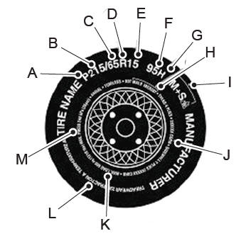
P215/65R15 95H is an example of a tire size, load index and speed rating. The definitions of these items are listed below. (Note that the tire size, load index and speed rating for your vehicle may be different from this example.)
P: Indicates a tire, designated by the Tire and Rim Association, that may be used for service on cars, sport utility vehicles, minivans and light trucks. Note: If your tire size does not begin with a letter this may mean it is designated by either the European Tire and Rim Technical Organization or the Japan Tire Manufacturing Association. 215: Indicates the nominal width of the tire in millimeters from sidewall edge to sidewall edge. In general, the larger the number, the wider the tire. 65: Indicates the aspect ratio which gives the tire's ratio of height to width. R: Indicates a radial type tire. 15: Indicates the wheel or rim diameter in inches. If you change your wheel size, you will have to purchase new tires to match the new wheel diameter. 95: Indicates the tire's load index. It is an index that relates to how much weight a tire can carry. You may find this information in your owner’s manual. If not, contact a local tire dealer.