Lincoln Corsair: Engine Cooling - 2.0L EcoBoost (177kW/240PS) – MI4 / Diagnosis and Testing - Engine Cooling
Special Tool(s)
|
Coolant/Battery Refractometer ROB75240 or equivalent |

|
D-Gas Adapter 300-OTC014-R1068 or equivalent |
|
Radiator Tester 014-R1072 or equivalent |

|
UView® Combustion Leak Tester UVU560000-R |
Diagnostic Trouble Code (DTC) Chart
 WARNING:
Before beginning any service procedure in this section,
refer to Safety Warnings in section 100-00 General Information. Failure
to follow this instruction may result in serious personal injury.
WARNING:
Before beginning any service procedure in this section,
refer to Safety Warnings in section 100-00 General Information. Failure
to follow this instruction may result in serious personal injury.
NOTICE: Use the correct coolant. Do not mix coolant types. Mixing coolant types may degrade the coolant corrosion protection and may damage the engine or cooling system. For the correct coolant specified for this vehicle, refer to specifications.
REFER to: Health and Safety Precautions (100-00 General Information, Description and Operation).
Diagnostics in this manual assume a certain skill level and knowledge of Ford-specific diagnostic practices.
REFER to: Diagnostic Methods (100-00 General Information, Description and Operation).
Diagnostic Trouble Code Chart
| Module | DTC | Description | Action |
|---|---|---|---|
| PCM | P0125:00 | Insufficient Coolant Temp For Closed Loop Fuel Control: No Sub Type Information | GO to Pinpoint Test C |
| PCM | P0128:00 | Coolant Thermostat (Coolant Temp Below Thermostat Regulating Temperature): No Sub Type Information | GO to Pinpoint Test C |
| PCM | P0217:00 | Engine Coolant Overtemperature Condition: No Sub Type Information | GO to Pinpoint Test B |
| PCM | P1299:00 | Cylinder Head Overtemperature Protection Active: No Sub Type Information | GO to Pinpoint Test B |
Global Customer Symptom Code (GCSC) Chart
Diagnostics in this manual assume a certain skill level and knowledge of Ford-specific diagnostic practices.
REFER to: Diagnostic Methods (100-00 General Information, Description and Operation).
| Symptom | Action |
|---|---|
| Driver Aid & Information > Warning Indicators/Messages/Chimes > Coolant > Stays On | GO to Pinpoint Test A |
| Driver Aid & Information > Warning Indicators/Messages/Chimes > Coolant > Stays On | GO to Pinpoint Test B |
| Start/Run/Move > Fluids > Coolant > Consumption | GO to Pinpoint Test A |
| Start/Run/Move > Fluids > Coolant > Consumption | GO to Pinpoint Test B |
| Start/Run/Move > Fluids > Coolant > Visible Leak | GO to Pinpoint Test A |
| Start/Run/Move > Fluids > Coolant > Visible Leak | GO to Pinpoint Test B |
Symptom Chart
Diagnostics in this manual assume a certain skill level and knowledge of Ford-specific diagnostic practices.
REFER to: Diagnostic Methods (100-00 General Information, Description and Operation).
| Condition | Possible Sources | Actions |
| Loss of coolant | Refer to the Pinpoint Test | GO to Pinpoint Test A |
| The engine overheats. | Refer to the Pinpoint Test | GO to Pinpoint Test B |
| The engine does not reach normal operating temperature. | Refer to the Pinpoint Test | GO to Pinpoint Test C |
| The electric cooling fan is inoperative in one or more speeds or does not operate correctly. |
|
|
| The electric cooling fan stays on all the time. |
|
Pinpoint Tests
|
Normal Operation and Fault Conditions The engine cooling system is a closed system providing for coolant expansion and contraction as well as changes in pressure as coolant warms and cools with engine operation. Various gaskets, seals, hoses and clamps contain coolant within the cooling system and keep other fluids and contaminants from entering the cooling system. Possible Sources
|
||||
| A1 CHECK COMPONENTS FOR DAMAGE OR FAILURE | ||||
Are any concerns present?
|
||||
| A2 CHECK THE ENGINE COOLANT LEVEL AND PRESSURE TEST THE ENGINE COOLING SYSTEM | ||||
|
NOTE: Allow the engine to cool before checking the engine coolant level.
Does the engine cooling system leak externally?
|
||||
| A3 CHECK THE ENGINE COOLANT FOR AN INTERNAL LEAK | ||||
Is engine oil evident in the engine coolant?
|
||||
| A4 CHECK THE ENGINE OIL FOR COOLANT | ||||
Is coolant evident in the oil?
|
||||
| A5 CHECK THE ENGINE COOLANT FOR TRANSMISSION FLUID | ||||
Is transmission fluid evident in the engine coolant?
|
||||
| A6 CHECK THE TRANSMISSION FLUID FOR ENGINE COOLANT | ||||
Is engine coolant evident in the transmission fluid?
|
||||
| A7 CHECK THE COOLING SYSTEM FOR COMBUSTION GASES | ||||
|
NOTE: Use UView® Combustion Leak Tester part number UVU560000-R or equivalent.
Are combustion gases present?
|
|
Normal Operation and Fault Conditions The engine cooling system maintains the engine temperature during operation. Correct coolant flow through the engine, radiator and remainder of cooling system passages and components is essential to maintaining a correct engine temperature. Engine coolant flows primarily from the engine to the radiator circuit and back to the coolant pump. Coolant is sent from the coolant pump through the engine block and cylinder heads. A separate circuit from the engine also feeds the heater core(s) and turbocharger with coolant. The coolant pump circulates the coolant. The coolant thermostat is a control valve actuated by coolant temperature. When the thermostat is closed, coolant flow bypasses the radiator circuit and returns to the coolant pump. When the thermostat is opened, coolant flows through the radiator circuit to transfer engine-generated heat to the outside air. Engine overheating generally occurs when there is a disruption in the ability to control either coolant flow at the correct rate, the inability to transfer heat from the engine through the coolant (including low coolant) or an inability to transfer engine-generated heat to the outside air through the radiator. DTC Fault Trigger Conditions
Possible Sources
|
|||||||||
| B1 CHECK COMPONENTS FOR DAMAGE OR FAILURE | |||||||||
Are any concerns present?
|
|||||||||
| B2 CHECK FOR PCM (POWERTRAIN CONTROL MODULE) DTCS | |||||||||
Is DTC P0217 and/or P1299 present?
|
|||||||||
| B3 CHECK FOR ACTIVE GRILL SHUTTER DTCS | |||||||||
Are any active grill shutter DTCs present?
|
|||||||||
| B4 CHECK FOR AN AIRFLOW OBSTRUCTION AND MISSING AIR DEFLECTORS | |||||||||
|
NOTE: Verify no vehicle front end damage is present.
Is an airflow obstruction present or air deflectors missing?
|
|||||||||
| B5 CHECK THE ENGINE COOLANT LEVEL AND PRESSURE TEST THE COOLING SYSTEM | |||||||||
Does the engine cooling system leak externally?
|
|||||||||
| B6 CHECK THE ENGINE COOLANT FOR AN INTERNAL LEAK | |||||||||
Is engine oil evident in the coolant?
|
|||||||||
| B7 CHECK THE ENGINE OIL FOR COOLANT | |||||||||
Is coolant evident in the oil?
|
|||||||||
| B8 CHECK THE ENGINE COOLANT FOR TRANSMISSION FLUID | |||||||||
Is transmission fluid evident in the engine coolant?
|
|||||||||
| B9 CHECK THE TRANSMISSION FLUID FOR ENGINE COOLANT | |||||||||
Is engine coolant evident in the transmission fluid?
|
|||||||||
| B10 CHECK THE COOLING SYSTEM FOR COMBUSTION GASES | |||||||||
|
NOTE: Use UView® Combustion Leak Tester part number UVU560000-R or equivalent.
Are combustion gases present?
|
|||||||||
| B11 CHECK COOLANT CONDITION | |||||||||
Is the coolant condition OK?
|
|||||||||
| B12 CHECK THE ELECTRIC COOLING FAN OPERATION | |||||||||
Did the electric cooling fan operate?
|
|||||||||
| B13 CHECK THE COOLANT PUMP OPERATION | |||||||||
Is the heater outlet hose hot?
|
|||||||||
| B14 CHECK THE THERMOSTAT OPERATION | |||||||||
|
NOTE: This cooling system uses a cold side thermostat. The coolant in the radiator must reach full operating temperature for the thermostat to remain in an open state.
Is the lower radiator hose hot?
|
|||||||||
| B15 VISUALLY INSPECT THE THERMOSTAT | |||||||||
Is the thermostat damaged?
|
|
Normal Operation and Fault Conditions The engine cooling system maintains engine temperature during operation. Correct coolant flow through the engine, radiator and remainder of cooling system passages and components is essential to maintaining a correct engine temperature. Engine coolant flows primarily from the engine to the radiator circuit and back to the coolant pump. Coolant is sent from the coolant pump through the engine block and cylinder head. A separate circuit from the engine also feeds the core(s) and turbocharger with coolant. The coolant pump circulates the coolant. The coolant thermostat is a control valve actuated by coolant temperature. When the thermostat is closed, coolant flow bypasses the radiator circuit and returns to the coolant pump. When the thermostat is opened, coolant flows through the radiator circuit in order to transfer engine generated heat to the outside air. Concerns of engine inability to reach normal operating temperature typically occur when the rate of coolant flow through some coolant circuits (radiator, heater core) is more than expected given the conditions. Heat is not allowed to build in the engine because a heat exchanger is removing too much heat, including the radiator, heater core and oil cooler (if equipped). In addition, perceived concerns that the engine does not reach normal operating temperature can be related to a low coolant level or trapped air which does not allow for hot coolant to be available at the heater core, an inoperative climate control system, or for concerns perceived or related to an incorrect engine temperature gauge indication. DTC Fault Trigger Conditions
Possible Sources
|
|||||||||
| C1 CHECK COMPONENTS FOR DAMAGE OR FAILURE | |||||||||
Were any concerns found?
|
|||||||||
| C2 CHECK FOR DTC P0125 OR P0128 | |||||||||
Is DTC P0125 or P0128 present?
|
|||||||||
| C3 CHECK THE COOLANT LEVEL | |||||||||
|
NOTE: Allow the engine to cool before checking the coolant expansion tank.
Is the engine coolant level within specification?
|
Component Tests
Cooling System Pressure Test
WARNING:
Always allow the engine to cool before opening the
cooling system. Do not unscrew the coolant pressure relief cap when the
engine is operating or the cooling system is hot. The cooling system is
under pressure; steam and hot liquid can come out forcefully when the
cap is loosened slightly. Failure to follow these instructions may
result in serious personal injury.
NOTE: Vehicles have a pressure relief cap on the degas bottle and no radiator cap.
-
Turn the engine OFF.
-
Check the coolant level and adjust as necessary.
-
Remove the degas bottle cap. Inspect the degas bottle
cap and degas bottle for any issues that would cause improper sealing,
such as for cross-threading, burrs, damaged o-ring, etc. If any issues
are found, or if coolant was expelled through the cap potentially
leaving contamination in the gasket, INSTALL a new cap and/or degas
bottle.
-
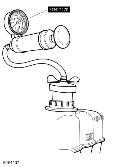
Attach the Pressure Tester and adaptor (Snap-On TA53 or
equivalent), to the degas bottle cap. The cap must hold pressure of 145
kPa +/- 21 kPa (21 PSI +/- 3 PSI). If any issues are found, INSTALL a
new cap.
-
Attach the Pressure Tester and adaptor (Snap-On TA52,
AST ASSFZ-47, Redline RDL95-0750 or equivalent) to the degas bottle.
-
NOTICE: Do not pressurize the cooling system beyond the maximum pressure listed in the Specifications table in this section or cooling system components may be damaged.
NOTE: If the plunger of the pressure tester is pressed too fast, an erroneous pressure reading results.
To pressurize the engine cooling system, slowly press the plunger of the pressure test pump and increase the pressure to between 124 - 138 kPa (18 - 20 PSI). Observe the gauge reading for approximately 2 minutes. Pressure should not drop during this time. If the pressure drops within this time, inspect for leaks and repair as necessary.
-
If no leaks are found and the pressure drops, the leak
may be internal to the engine. Inspect the coolant for engine oil and
the engine oil for coolant.
REFER to: Engine (303-00 Engine System - General Information, Diagnosis and Testing).
-
If the pressure does not drop remove the cooling system Pressure Tester and adaptor from degas bottle.
-
Install the degas bottle cap until it contacts the hard stop.
Thermostat
Install a new thermostat only after at least one of the following tests and checks have been carried out:
- Pinpoint Test B or C
- Thermostat Visual Inspection
Thermostat Visual Inspection
-
Remove the thermostat.
-
Examine the thermostat for signs of damage including:
- Valve not fully seated (light visible through the valve)
- Foreign material lodged in the main valve
- Bent or broken frame or flange
- Bent or broken spring
- Wax leaking from wax reservoir or a bulge in the reservoir
- Any other damage or distortion
- Worn O-ring seal
-
NOTE: If no damage is found during the inspection, do not attempt to open the thermostat using hot water or other heat sources. This method is not an accurate means to test the function of the thermostat and may damage the thermostat.
If damage is found during the inspection, remove any foreign material or broken pieces and install a new thermostat.
Radiator Leak Test, Removed From Vehicle
NOTICE: Never leak test an aluminum radiator in the same water that copper/brass radiators are tested in. Flux and caustic cleaners may be present in the cleaning tank and they will damage aluminum radiators.
NOTE: Clean the radiator before leak testing to avoid contamination of tank.
-
Leak test the radiator in clean water with air
pressurized to the maximum pressure listed in the Specifications table.
 Diagnosis and Testing - Cooling Fan Control
Diagnostic Trouble Code (DTC) Chart
Diagnostics in this manual assume a certain skill level and knowledge of Ford-specific diagnostic practices.REFER to: Diagnostic Methods (100-00 General Information, Description and Operation)...
 Diagnosis and Testing - Engine Temperature
Diagnostic Trouble Code (DTC) Chart
Diagnostics in this manual assume a certain skill level and knowledge of Ford-specific diagnostic practices. REFER to: Diagnostic Methods (100-00 General Information, Description and Operation)...
Other information:
Lincoln Corsair 2020-2026 Service Manual: Description and Operation - Four-Wheel Drive Systems - Overview
NOTE: The AWD system may be referred to as a 4WD system or Active Torque Coupling (ATC) system in other service information, owner literature, or messages located on the message center. The All Wheel Drive Systems consists of the following: PTU (Power Transfer Unit) RDU Driveline Control Module (DLCM) The Power Transfer Unit (PTU) system consists of ..
Lincoln Corsair 2020-2026 Service Manual: General Procedures - Power Transfer Unit Draining and Filling
Materials Name Specification Motorcraft® SAE 75W-85 Premium Synthetic Hypoid Gear LubricantXY-75W85-QL WSS-M2C942-A Draining With the vehicle in NEUTRAL, position it on a hoist. Refer to: Jacking and Lifting - Overview (100-02 Jacking and Lifting, Description and Operation). Remove the underbody shield. Refer to: Engine Front Undershield (501-..
Categories
- Manuals Home
- 1st Generation Lincoln Corsair Owners Manual
- 1st Generation Lincoln Corsair Service Manual
- Memory Function
- Refueling - Gasoline
- General Procedures - Brake Service Mode Activation and Deactivation
- New on site
- Most important about car
Creating a Vehicle Wi-Fi Hotspot
You can create a Wi-Fi hotspot in your vehicle and allow devices to connect to it for access to the Internet.
 Select the settings option on
the
feature bar.
Select the settings option on
the
feature bar.