Lincoln Corsair: Electronic Engine Controls - 2.0L EcoBoost (177kW/240PS) – MI4 / Description and Operation - Electronic Engine Controls - Component Location
Lincoln Corsair 2020-2026 Service Manual / Powertrain / Engine / Electronic Engine Controls - 2.0L EcoBoost (177kW/240PS) – MI4 / Description and Operation - Electronic Engine Controls - Component Location
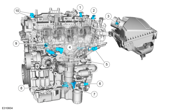
Electronic Engine Controls- Front
| Item | Description |
|---|---|
| 1 | ExhaustCMP sensor |
| 2 | Intake CMP sensor |
| 3 | IAT sensor |
| 4 | MAPT sensor |
| 5 | KS |
| 6 | EOP sensor |
| 7 | Turbocharger Boost Pressure Sensor |
| 8 | Oil pressure control solenoid |
| 9 | FRP sensor |
| 10 | VCT oil control solenoids |
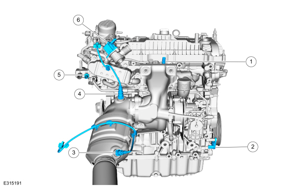
Electronic Engine Controls - Rear
| Item | Description |
|---|---|
| 1 | CHT (CHT2) sensor |
| 2 | CKP sensor |
| 3 | Catalyst monitor sensor |
| 4 | HO2S |
| 5 | ECT sensor |
| 6 | Turbocharger bypass valve |
Powertrain Control Module (PCM)

| Item | Description |
|---|---|
| 1 | PCM |
 Specifications
Reference Value Symptom Chart
NOTE:
The Reference Value Symptom Chart provides guidance in
selecting the appropriate parameter identification (PID) or measured
signal related to the fault area...
 Description and Operation - Electronic Engine Controls - Overview
Overview
The
EEC system provides optimum control of the engine through the enhanced
capability of the powertrain control module (PCM). The EEC system also
has an on board diagnostic (OBD) monitoring system with features and
functions to meet federal regulations on exhaust emissions...
Other information:
Lincoln Corsair 2020-2026 Owners Manual: Anti-Theft Alarm System Settings
What are the Alarm Security Levels You can select two levels of alarm security, all sensors and perimeter sensing. All Sensors All sensors is the standard setting. In all sensors, all equipped sensors are on when you arm the alarm. Note: Do not arm the alarm with all sensors if passengers, animals or other moving objects are inside your vehicle...
Lincoln Corsair 2020-2026 Owners Manual: Driver and Passenger Knee Airbags. Safety Canopy™
Driver and Passenger Knee Airbags Driver and passenger knee airbags are located under or within the instrument panel. During a crash, the restraints control module may activate the driver and passenger knee airbags (individually or both) based on crash severity and respective occupant conditions...
Categories
- Manuals Home
- 1st Generation Lincoln Corsair Owners Manual
- 1st Generation Lincoln Corsair Service Manual
- Opening and Closing the Hood
- Overhaul - Main Control Valve Body
- Fuel Quality - Gasoline
- New on site
- Most important about car
Creating a Vehicle Wi-Fi Hotspot
You can create a Wi-Fi hotspot in your vehicle and allow devices to connect to it for access to the Internet.
 Select the settings option on
the
feature bar.
Select the settings option on
the
feature bar.
Copyright © 2026 www.licorsair.com