Lincoln Corsair: Rear Electric Drive Assembly / Removal and Installation - Rear Electric Drive Assembly
Special Tool(s) /
General Equipment
| Transmission Jack |
| Fluid Container |
| Retaining Strap |
| Locking Pliers |
Removal
-
 WARNING:
To prevent the risk of high-voltage shock, always
follow precisely all warnings and service instructions, including
instructions to depower the system. The high-voltage system utilizes
approximately 450 volts DC, provided through high-voltage cables to its
components and modules. The high-voltage cables and wiring are
identified by orange harness tape or orange wire covering. All
high-voltage components are marked with high-voltage warning labels with
a high-voltage symbol. Failure to follow these instructions may result
in serious personal injury or death.
WARNING:
To prevent the risk of high-voltage shock, always
follow precisely all warnings and service instructions, including
instructions to depower the system. The high-voltage system utilizes
approximately 450 volts DC, provided through high-voltage cables to its
components and modules. The high-voltage cables and wiring are
identified by orange harness tape or orange wire covering. All
high-voltage components are marked with high-voltage warning labels with
a high-voltage symbol. Failure to follow these instructions may result
in serious personal injury or death.
De-energize the high-voltage system.
Refer to: High Voltage System De-energizing (414-03A High Voltage Battery, Mounting and Cables, General Procedures).
-
Disconnect the battery ground cable.
Refer to: Battery Disconnect and Connect (414-01 Battery, Mounting and Cables, General Procedures).
-
If necessary, drain the rear electric drive assembly oil.
Use the General Equipment: Fluid Container
-
Remove the following items:
-
Remove the muffler and tailpipe.
Refer to: Muffler and Tailpipe (309-00C Exhaust System - 2.5L Duratec – Hybrid (121kW/164PS) (BG), Removal and Installation).
-
Remove the rear halfshafts.
Refer to: Rear Halfshaft (205-05 Rear Drive Halfshafts, Removal and Installation).
-
Remove the bolt for the high-voltage battery wire harness.
-
Remove the bolts and position aside the high-voltage battery wire harness.
-
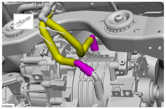
-
Clamp the cooling hoses to the rear electric drive assembly.
Use the General Equipment: Locking Pliers
-
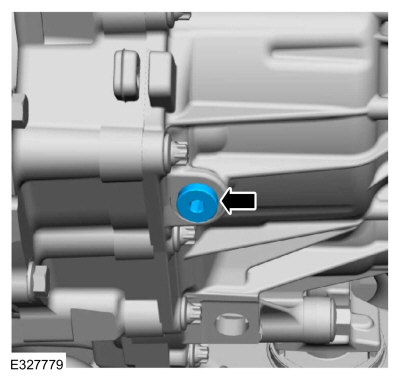
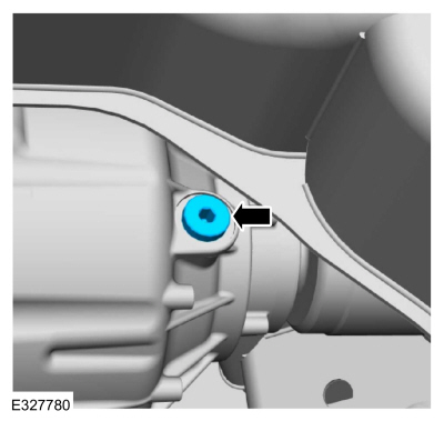
Remove the bolt and position aside the ground wire.
-
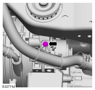
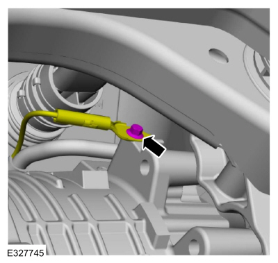
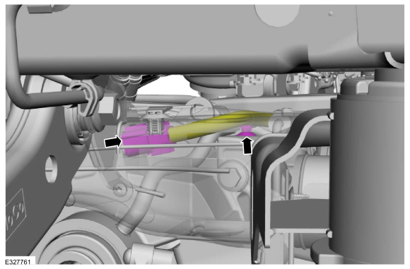
Disconnect the motor vent hose and position aside.
-
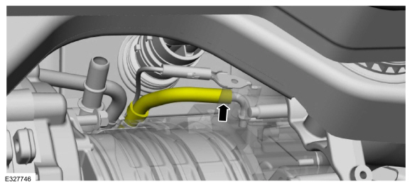
Disconnect the axle vent hose and position aside.
-
Disconnect the electrical connector and the wire retainer.
-
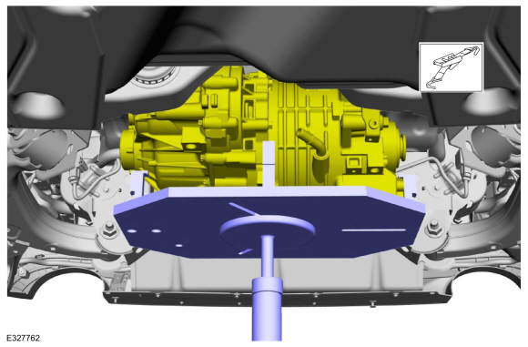
WARNING:
Always secure engines, transmissions, or other heavy
components to the support fixture with straps and wooden support
blocks. Improperly secured assemblies could fall off the fixture,
resulting in serious personal injury.
Using a transmission jack, support the rear electric drive assembly. Install a safety strap.
Use the General Equipment: Transmission Jack
Use the General Equipment: Retaining Strap
-
-
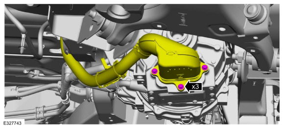
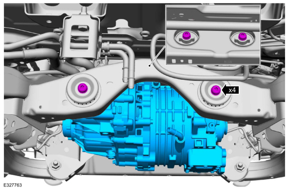
NOTE:
Loosen the bolt completely and leave in place during the removal and installation.
Loosen the rear bolts and position them out.
-
Remove the front bolts and lower the rear electric drive assembly from the vehicle.
-
If necessary, remove the bolts and the mounting brackets.
Installation
-
If necessary, install the mounting brackets and the bolts.
Torque:
66 lb.ft (90 Nm)
-
Install the rear electric drive assembly and the bolts.
Torque:
66 lb.ft (90 Nm)
-
Remove the safety strap and the transmission jack.
Use the General Equipment: Transmission Jack
Use the General Equipment: Retaining Strap
-
Connect the electrical connector and the wire retainer.
-
Position back and connect the axle vent hose.
-
Position back and connect the motor vent hose.
-
Position back the ground wire and install the bolt.
Torque:
106 lb.in (12 Nm)
-
-
Connect the rear electric drive assembly cooling hoses.
Use the General Equipment: Fluid Container
-
Remove the locking pliers for the cooling hoses to the rear electric drive assembly.
Use the General Equipment: Locking Pliers
-
Position back the high-voltage battery wire harness and install the bolts.
Torque:
97 lb.in (11 Nm)
-
Install the bolt for the high-voltage battery wire harness.
Torque:
97 lb.in (11 Nm)
-
Install the following items:
-
Install the rear halfshafts.
Refer to: Rear Halfshaft (205-05 Rear Drive Halfshafts, Removal and Installation).
-
Install the muffler and tailpipe.
Refer to: Muffler and Tailpipe (309-00C Exhaust System - 2.5L Duratec – Hybrid (121kW/164PS) (BG), Removal and Installation).
-
Connect the battery ground cable.
Refer to: Battery Disconnect and Connect (414-01 Battery, Mounting and Cables, General Procedures).
-
Repower the high-voltage system.
Refer to: High Voltage System De-energizing (414-03A High Voltage Battery, Mounting and Cables, General Procedures).
-
Fill and bleed the electric powertrain cooling system.
Refer to: Cooling System Filling and Bleeding (303-03D Electric
Powertrain Cooling - 2.5L Duratec – Hybrid (121kW/164PS) (BG), General
Procedures).
-
NOTE:
This step is not necessary when installing a new component.
Remove the fill plug and fill the front electric drive assembly oil. Install the fill plug.
Refer to: Specifications (302-02 Rear Electric Drive Assembly)
.
Torque:
177 lb.in (20 Nm)
-
Carry out a road test.
-
Remove the fill plug. Check and top off the front electric drive assembly oil level. Install the fill plug.
Refer to: Specifications (302-02 Rear Electric Drive Assembly)
.
Torque:
177 lb.in (20 Nm)
-
NOTE:
This step is only necessary when installing a new component.
Using the scan tool, CARRY OUT the Electric Motor Resolver Offset Programming in the SOBDMB .
Refer to: Electric Drive Assembly Strategy Download (302-02 Rear Electric Drive Assembly, General Procedures).
-
NOTE:
This step is only necessary when installing a new S-ISC (secondary-inverter system controller) - SOBDMB .
Perform the PATS initialization procedure.
Refer to: Module Programming (418-01 Module Configuration, General Procedures).
Special Tool(s) /
General Equipment
Ford Diagnostic Equipment
Fluid Container
Removal
With the vehicle in NEUTRAL, position it on a hoist...
Other information:
Special Tool(s) /
General Equipment
Hydraulic Press
Removal
Remove the wheel bearing and wheel hub.
Refer to: Wheel Bearing and Wheel Hub - AWD (204-02 Rear Suspension, Removal and Installation).
Refer to: Wheel Bearing and Wheel Hub - FWD (204-02 Rear Suspension, Removal and Installation).
Press the wheel stud from the wheel bearing and wheel hub flange.
U..
Special Tool(s) /
General Equipment
204-161
(T97P-1175-A)
Installer, HalfshaftTKIT-1997-LM2TKIT-1997-F/FM2TKIT-1997-FLM2
205-D070
(D93P-1175-B)
Remover, Front Wheel Hub
Tie Rod End Remover
Removal
NOTICE:
Suspension fasteners are critical parts that affect the
performance of vital components and systems. Failure of these fasteners
may result in major service expe..
 Removal and Installation - Inverter System Controller [SOBDMB]
 Engine