Lincoln Corsair: Supplemental Restraint System / Removal and Installation - Occupant Classification System (OCS) Sensor
Special Tool(s) / General Equipment
| Flat Headed Screw Driver |
Removal
.jpg) WARNING:
The following procedure prescribes critical repair steps
required for correct restraint system operation during a crash. Follow
all notes and steps carefully. Failure to follow step instructions may
result in incorrect operation of the restraint system and increases the
risk of serious personal injury or death in a crash.
WARNING:
The following procedure prescribes critical repair steps
required for correct restraint system operation during a crash. Follow
all notes and steps carefully. Failure to follow step instructions may
result in incorrect operation of the restraint system and increases the
risk of serious personal injury or death in a crash.
NOTICE: To prevent system failure, carry out the OCS (occupant classification system) reset when a front passenger seat cushion is disassembled, a new trim cover or heater mat is installed or an OCS (occupant classification system) service kit is installed. Use a diagnostic scan tool to carry out the OCS (occupant classification system) reset command.
NOTE: OCS (occupant classification system) components (seat cushion foam, bladder with OCSM (occupant classification system module)) are calibrated to each other and are serviced as an assembly with an OCS (occupant classification system) service kit. If a new OCS (occupant classification system) or seat cushion foam are needed, a new OCS (occupant classification system) service kit must be installed. The heater mat can be serviced separately.
NOTE: Removal steps in this procedure may contain installation details.
-
Refer to: Pyrotechnic Device Health and Safety Precautions (100-00 General Information, Description and Operation).
WARNING:
Before beginning any service procedure in this
manual, refer to health and safety warnings in section 100-00 General
Information. Failure to follow this instruction may result in serious
personal injury.
-
Remove the front passenger seat.
Refer to: Front Seat (501-10A Front Seats, Removal and Installation).
-
Detach the electrical connectors, the wiring harness
retainers and position the front seat wiring harnesses aside.
.jpg) |
-
Release the front seat backrest panel straps.
.jpg) |
-
Detach the front seat cushion cover rear retainers and position the cushion cover aside.
.jpg) |
-
If equipped with heated seat.
Disconnect the front seat cushion heater mat electrical connector and detach the wiring harness pin-type retainer.
.jpg) |
-
-
Disconnect the OCSM electrical connector.
-
NOTICE: Using excessive force when bending the bracket tab can damage the OCS (occupant classification system) sensor housing.
NOTE: Follow the unique instructions or graphic for this step in the installation.
Bend the OCSM bracket tab up. Use the General Equipment: Flat Headed Screw Driver
-
Slide the OCSM off the bracket.
-
Disconnect the OCSM electrical connector.
.jpg) |
-
Remove the front seat side shield screws.
.jpg) |
-
Remove the front seat RH side shield.
-
Firmly grasp the front seat side shield, lift up and
out, separating the front seat side shield from the recliner bracket.
-
Slide the side shield forward and separate the side shield from the seat.
-
Firmly grasp the front seat side shield, lift up and
out, separating the front seat side shield from the recliner bracket.
.jpg) |
-
Remove the front seat LH side shield.
-
Firmly grasp the front seat side shield, lift up and
out, separating the front seat side shield from the recliner bracket.
-
Slide the side shield forward and separate the side shield from the seat.
-
Firmly grasp the front seat side shield, lift up and
out, separating the front seat side shield from the recliner bracket.
.jpg) |
-
Remove the screws and the front seat valance.
.jpg) |
-
-
Detach the front seat cushion cover J-clip.
-
On both sides.
Detach the front seat cushion cover J-clips.
-
Detach the front seat cushion cover J-clip.
.jpg) |
-
Lift the front seat cushion foam. If the cushion foam and the OCS are
adhered together, then the OCS is a service kit. If nothing is adhered
together, then the OCS is OE (original equipment).
.jpg) |
-
If equipped with OE (original equipment) OCS , remove the front seat cushion foam pad and cover.
.jpg) |
-
NOTE: Typical OE (original equipment) OCS (occupant classification system) shown, service kit similar.
-
Detach the OCS bladder pin-type retainers..
-
Lift the OCS bladder off the front seat track.
-
Detach the OCS bladder pin-type retainers..
.jpg) |
-
NOTE: Note the location of the OCS (occupant classification system) hose as it passes through the seat springs for proper installation.
Route out the OCSM and hose from between the front seat cushion support wires and remove the OCS .
.jpg) |
-
NOTE: This step is only necessary when installing a new OCS (occupant classification system).
Position the rear portion of the front seat cushion cover from the foam.
.jpg) |
-
NOTICE: Use care when separating the seat cushion trim cover from the hook-and-loop strips or the hook-and-loop strips may be torn from the seat cushion foam pad.
NOTICE: Use care when separating the seat cushion trim cover from the hook-and-arrow or the hook may be torn from the seat cushion foam pad.
NOTE: This step is only necessary when installing a new OCS (occupant classification system).
NOTE: Follow the unique instructions or graphic for this step in the installation.
Remove the front seat cushion cover.
-
Invert the front seat cushion cover.
-
Release the hook-and-loop strips.
-
Release the hook and arrows.
-
Release the hook-and-loop strip.
-
Invert the front seat cushion cover.
.jpg) |
Installation
-
NOTICE: Inspect the OCS (occupant classification system) bladder, seat cushion pan and support assembly for any foreign objects before installing the OCS (occupant classification system) to the seat cushion pan. Remove any foreign objects. Failure to follow these instructions may result in incorrect operation of the OCS (occupant classification system) and may cause system failure.
NOTICE: Do not trap the pressure sensor hose incorrectly over the seat's suspension or spring. Route the hose so that it lays in a natural bend, and is not twisted due to being forced into an unnatural position. Failure to follow these instructions may result in component damage and/or system failure.
To install, reverse the removal procedure.
-
If required.
Install a new cushion heater mat.
Refer to: Seat Heater Mat Installation (501-10A Front Seats, General Procedures).
-
Bend the OCS sensor bracket tab back.
.jpg) |
-
Install the front passenger seat. Do not prove out the SRS at this time.
Refer to: Front Seat (501-10A Front Seats, Removal and Installation).
-
WARNING:
Occupant Classification System (OCS) parts are
calibrated as an assembly and must only be replaced in the configuration
they are sold. Never separate parts of an assembly. Failure to follow
this instruction may result in incorrect operation of the OCS and
increases the risk of serious personal injury or death in a crash.
WARNING:
Make sure the front passenger seat repair is
complete, the seat and all attached components (head restraint, seat
side shield, etc.) are correctly assembled, and the seat is correctly
installed to the vehicle before using System Reset to rezero the seat
weight. Failure to follow these instructions may result in incorrect
operation of the occupant classification system (OCS) and increases the
risk of serious personal injury or death in a crash.
NOTICE: To prevent system failure, take the following precautions before carrying out the OCS (occupant classification system) reset.
- Make sure the voltage to the OCSM (occupant classification system module) is greater than 8 volts and less than 18 volts.
- Make sure the OCS (occupant classification system) is not below 6º C (42.8º F) or above 36º C (96.7º F) when initiating the OCS (occupant classification system) reset process. If the vehicle has been exposed to extreme cold or hot temperatures, the vehicle must be exposed and kept at a temperature between 6º C (42.8º F) to 36º C (96.7º F) for a minimum of 30 minutes.
- Make sure nothing is present on the passenger seat before and during the OCS (occupant classification system) reset process.
- Prior to carrying out the OCS (occupant classification system) reset, make sure a minimum of 8 seconds has elapsed after cycling the ignition switch on.
-
If the first system reset attempt was successful, proceed to prove out the SRS .
-
If the first system reset attempt was not successful, carry out a thorough visual inspection of the OCS
connector and wiring for damage, pressure sensor hose for kinks and or
damage, and seat-related wiring harness and body wiring harness
terminals and connectors for damage. Repair any concerns found and
proceed to the next step.
-
Carry out a second OCS reset. Cycle the ignition switch after the OCS
reset. If the second attempt is unsuccessful, install a new OCS service
kit.
-
Prove out the SRS
. Verify all airbags are installed and connected and the ignition is
OFF. Wait 10 seconds then turn the ignition ON and monitor the airbag
warning indicator. The airbag warning indicator illuminates continuously
for approximately 6 seconds and turns off. Continue to monitor the
airbag warning indicator for approximately 30 seconds, as this is the
time required for the RCM to complete testing of the SRS .
-
If a SRS
fault is present, the airbag warning indicator either fails to light,
remains lit continuously or flashes. The flashing may not occur until
approximately 30 seconds after the ignition has been turned from OFF to
ON. If this occurs, diagnose and repair any SRS faults before proceeding with other repairs.
-
If, after the ignition has been turned on for 30
seconds, the airbag warning indicator remains unlit with no chime or SRS
message displayed in the message center, no SRS fault is present.
-
If the airbag warning indicator is inoperative and a SRS
fault exists, a chime sounds in a pattern of 5 sets of 5 beeps or a
message displays in the message center. If this occurs, diagnose and
repair the airbag warning indicator and any SRS faults before proceeding with other repairs.
-
If a SRS
fault is present, the airbag warning indicator either fails to light,
remains lit continuously or flashes. The flashing may not occur until
approximately 30 seconds after the ignition has been turned from OFF to
ON. If this occurs, diagnose and repair any SRS faults before proceeding with other repairs.
-
Using a scan tool, clear all Continuous Memory Diagnostic Trouble Codes (CMDTCs) from all modules.
 Removal and Installation - Front Impact Severity Sensor
Removal
WARNING:
The following procedure prescribes critical repair steps
required for correct restraint system operation during a crash. Follow
all notes and steps carefully...
 Removal and Installation - Occupant Classification System (OCS) Sensor - Vehicles With: Multi-Contour Seats
Special Tool(s) /
General Equipment
Flat Headed Screw Driver
Removal
WARNING:
The following procedure prescribes critical repair steps
required for correct restraint system operation during a crash...
Other information:
Lincoln Corsair 2020-2024 Service Manual: Description and Operation - Electric Powertrain Control - Component Location
Inverter System Controller Item Description 1 Inverter System Controller High Voltage Battery Coolant Temperature Sensor Item Description 1 High Voltage Battery Coolant Temperature Sensor ..
Lincoln Corsair 2020-2024 Service Manual: General Procedures - Fixed Glass
Special Tool(s) / General Equipment Power Caulk Gun Power Fixed Glass Removal Tool Cold Knife Knife Vacuum Cleaner Materials Name Specification Sika® SikaTack® MACH 60 / Sika® SikaTack® MACH 30 / Dow® BETASEAL™ Express - Sika Tack ASAP Urethane Adhesive - Motorcraft® Ultra-Clear Spray Glass CleanerZC-23 ESR-M14P5-A ..
Categories
- Manuals Home
- 1st Generation Lincoln Corsair Owners Manual
- 1st Generation Lincoln Corsair Service Manual
- Warning Lamps and Indicators
- Selecting a Drive Mode. DRIVE MODES
- Auto-Start-Stop
- New on site
- Most important about car
Information on P Type Tires
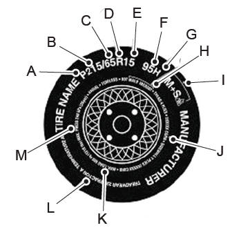
P215/65R15 95H is an example of a tire size, load index and speed rating. The definitions of these items are listed below. (Note that the tire size, load index and speed rating for your vehicle may be different from this example.)
P: Indicates a tire, designated by the Tire and Rim Association, that may be used for service on cars, sport utility vehicles, minivans and light trucks. Note: If your tire size does not begin with a letter this may mean it is designated by either the European Tire and Rim Technical Organization or the Japan Tire Manufacturing Association. 215: Indicates the nominal width of the tire in millimeters from sidewall edge to sidewall edge. In general, the larger the number, the wider the tire. 65: Indicates the aspect ratio which gives the tire's ratio of height to width. R: Indicates a radial type tire. 15: Indicates the wheel or rim diameter in inches. If you change your wheel size, you will have to purchase new tires to match the new wheel diameter. 95: Indicates the tire's load index. It is an index that relates to how much weight a tire can carry. You may find this information in your owner’s manual. If not, contact a local tire dealer.