Lincoln Corsair: Supplemental Restraint System / Removal and Installation - Front Impact Severity Sensor
Removal
.jpg) WARNING:
The following procedure prescribes critical repair steps
required for correct restraint system operation during a crash. Follow
all notes and steps carefully. Failure to follow step instructions may
result in incorrect operation of the restraint system and increases the
risk of serious personal injury or death in a crash.
WARNING:
The following procedure prescribes critical repair steps
required for correct restraint system operation during a crash. Follow
all notes and steps carefully. Failure to follow step instructions may
result in incorrect operation of the restraint system and increases the
risk of serious personal injury or death in a crash.
NOTE: Removal steps in this procedure may contain installation details.
-
Refer to: Pyrotechnic Device Health and Safety Precautions (100-00 General Information, Description and Operation).
WARNING:
Before beginning any service procedure in this
manual, refer to health and safety warnings in section 100-00 General
Information. Failure to follow this instruction may result in serious
personal injury.
-
Depower the SRS .
Refer to: Supplemental Restraint System (SRS) Depowering (501-20B Supplemental Restraint System, General Procedures).
-
Remove the pin-type retainers, release the tabs and remove the air cleaner inlet pipe.
.jpg) |
-
Remove the front impact severity sensor(s).
-
Remove the bolt(s).
Torque: 93 lb.in (10.5 Nm)
-
Disconnect the electrical connector(s).
-
Remove the front impact severity sensor(s).
-
Remove the bolt(s).
.jpg) |
Installation
-
NOTE: The front impact severity sensor mating surfaces must be smooth and allow for a flush attachment to each other.
To install, reverse the removal procedure.
-
Repower the SRS .
Refer to: Supplemental Restraint System (SRS) Repowering (501-20B Supplemental Restraint System, General Procedures).
 Removal and Installation - Front Door Side Impact Sensor
Removal
WARNING:
The following procedure prescribes critical repair steps
required for correct restraint system operation during a crash. Follow
all notes and steps carefully...
 Removal and Installation - Occupant Classification System (OCS) Sensor
Special Tool(s) /
General Equipment
Flat Headed Screw Driver
Removal
WARNING:
The following procedure prescribes critical repair steps
required for correct restraint system operation during a crash...
Other information:
Lincoln Corsair 2020-2024 Service Manual: Removal and Installation - Front Suspension Height Sensor
Special Tool(s) / General Equipment 6.5 mm Drill Bit Rivet Gun Electric Drill Removal NOTE: Removal steps in this procedure may contain installation details. Remove the wheel and tire. Refer to: Wheel and Tire (204-04A Wheels and Tires, Removal and Installation)...
Lincoln Corsair 2020-2024 Service Manual: General Procedures - Starter Amperage Draw Test
NOTE: Make sure the test is performed with the engine at 60.8 °F ( 16 °C) or above. Make sure the battery is fully charged. For additional information, refer to: Specifications (414-01 Battery, Mounting and Cables, Specifications)...
Categories
- Manuals Home
- 1st Generation Lincoln Corsair Owners Manual
- 1st Generation Lincoln Corsair Service Manual
- Programming the Garage Door Opener to Your Garage Door Opener Motor
- Refueling - Gasoline
- Fuel Quality - Gasoline
- New on site
- Most important about car
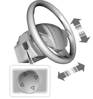
Adjusting the Steering Wheel - Vehicles With: Power Adjustable Steering Column
WARNING: Do not adjust the steering wheel when your vehicle is moving.
Note: Make sure that you are sitting in the correct position.