Lincoln Corsair: Front Suspension / Removal and Installation - Front Strut and Spring Assembly
Removal
NOTICE: Suspension fasteners are critical parts that affect the performance of vital components and systems. Failure of these fasteners may result in major service expense. Use the same or equivalent parts if replacement is necessary. Do not use a replacement part of lesser quality or substitute design. Tighten fasteners as specified.
NOTE: Removal steps in this procedure may contain installation details.
-
Remove the wheel and tire.
Refer to: Wheel and Tire (204-04A Wheels and Tires, Removal and Installation).
-
NOTICE: Do not use power tools to remove or install the stabilizer bar link nuts. Damage to the stabilizer bar link ball joints and boots may occur.
NOTE: Use the TORX PLUS® holding feature to prevent the ball stud from turning while removing or installing the lower arm outboard nut. Torx® and TORX PLUS® is a reg. tm of Acument Intellectual Properties, LLC.
NOTE: The stabilizer bar links are designed with low friction ball joints that have a low breakaway torque.
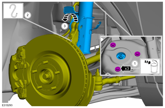
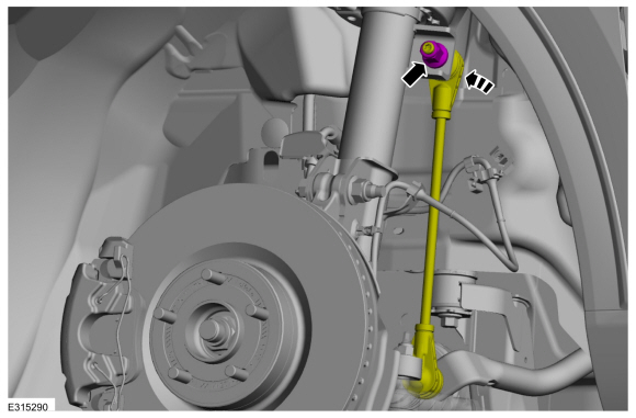
Remove and discard the upper stabilizer bar link nut and position aside the stabilizer bar link.
 |
-
-
NOTICE: Note the routing of the lines and hoses.
Remove the bolt and position aside the brake hose.
-
Unclip the 2 wire retainers and position aside the wheel speed sensor wiring harness.
-
 |
-
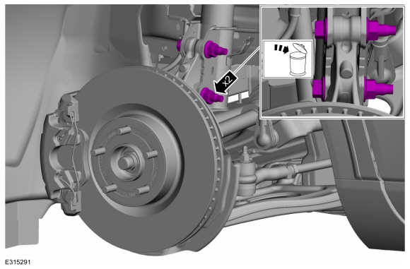
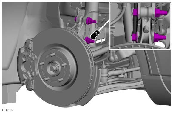
Remove and discard the 2 front strut and spring assembly-to-wheel knuckle bolts and nuts.
 |
-
Remove the cowl panel grille.
Refer to: Cowl Panel Grille (501-02 Front End Body Panels, Removal and Installation).
-
Remove cowl panel grille support bracket retainers and bracket.
 |
-
-
Remove and discard the 3 top front strut and spring assembly mounting bolts.
-
NOTICE: Make sure that no load is placed on the brake hose.
NOTICE: Never allow the knuckle to hang from the upper and lower control arms or damage to the ball joints can occur.
NOTE: Take care not to damage coating on suspension components.
Support the wheel knuckle assembly using mechanic's wire.
-
Remove the front strut and spring assembly.
-
Remove and discard the 3 top front strut and spring assembly mounting bolts.
 |
Installation
NOTICE: Tighten the suspension fasteners with the weight of the vehicle on the wheels and tires or use a suitable jack to raise the suspension to curb height or damage to the bushings may occur.
-
To install, reverse the removal procedure.
-
-
Position the front strut and spring assembly into the wheel knuckle.
-
Install the new front strut and spring assembly upper bolts.
Torque: 26 lb.ft (35 Nm)
-
Position the front strut and spring assembly into the wheel knuckle.
 |
-
Install the new front strut and spring assembly-to-wheel knuckle bolts and nuts.
Torque:
Stage 1: 103 lb.ft (140 Nm)
Stage 2: 120°
 |
-
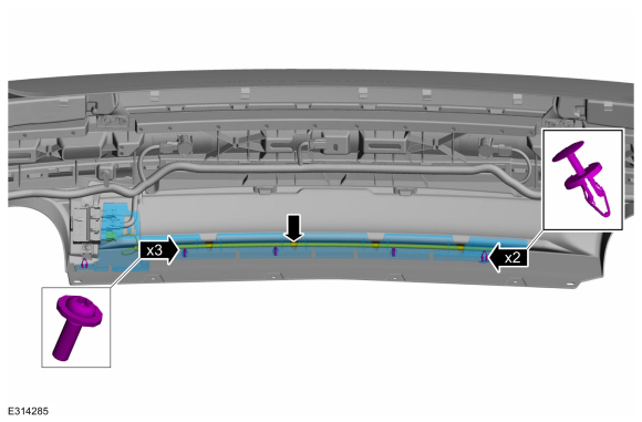
Install the cowl panel grille support bracket and retainers.
Torque: 22 lb.in (2.5 Nm)
|
-
Install the cowl panel grille.
Refer to: Cowl Panel Grille (501-02 Front End Body Panels, Removal and Installation).
-
-
NOTICE: Make sure that the brake hose is not twisted and is correctly located.
Position the brake hose and install the bolt.
Torque: 97 lb.in (11 Nm)
-
Position the wheel speed sensor wiring harness and clip the 2 wire retainers.
-
|
-
NOTICE: Do not use power tools to remove or install the stabilizer bar link nuts. Damage to the stabilizer bar link ball joints and boots may occur.
NOTE: Use the TORX PLUS® holding feature to prevent the ball stud from turning while removing or installing the lower arm outboard nut. Torx® and TORX PLUS® is a reg. tm of Acument Intellectual Properties, LLC.
NOTE: The stabilizer bar links are designed with low friction ball joints that have a low breakaway torque.
Position the front stabilizer bar link and install the new front stabilizer bar link upper nut.
Torque: 81 lb.ft (110 Nm)
 |
-
Install the wheel and tire.
Refer to: Wheel and Tire (204-04A Wheels and Tires, Removal and Installation).
-
For additional information on the disassembly and assembly of the strut and spring assembly.
Refer to: Front Strut and Spring Assembly (204-01 Front Suspension, Disassembly and Assembly).
 Removal and Installation - Front Stabilizer Bar Link
Removal
NOTICE:
Suspension fasteners are critical parts that affect the
performance of vital components and systems. Failure of these fasteners
may result in major service expense...
 Removal and Installation - Front Wheel Bearing and Wheel Hub
Special Tool(s) /
General Equipment
204-023
(T73T-1217-A)
Installer, Wheel Hub Bearing Cup
204-180
(T93P-5493-A)
Remover/Installer, BushingTKIT-1993-FLMTKIT-1993-LMTKIT-1993-FM
205-138
(T80T-4000-D)
Installer, Drive Pinion Bearing Cup
205-140
(T80T-4000-F)
Installer, Drive Pinion Bearing Cup
205-153
(T80T-4000-W)
Handle
205-480Installer, Drive Pi..
Other information:
Lincoln Corsair 2020-2024 Service Manual: Description and Operation - External Controls - System Operation and Component Description
System Diagram Item Description 1 GSM 2 GWM 3 RCM 4 IPC 5 PCM 6 BCM 7 Driver 8 Door 9 Latch 10 Brake 11 On/Off (BOO) 12 Switch Network Message Chart Broadcast Message Originating Module Message Purpose Brake switch position BCM Input from brake switch necessary to change gears. ..
Lincoln Corsair 2020-2024 Service Manual: Removal and Installation - Exhaust Gas Recirculation (EGR) Valve
Removal NOTE: Removal steps in this procedure may contain installation details. Remove the differential pressure feedback EGR sensor. Refer to: Differential Pressure Feedback Exhaust Gas Recirculation (EGR) Sensor (303-08A Engine Emission Control - 2.0L EcoBoost (177kW/240PS) – MI4, Removal and Installation). Drain the cooling system. Refer to: Engine Cooling ..
Categories
- Manuals Home
- 1st Generation Lincoln Corsair Owners Manual
- 1st Generation Lincoln Corsair Service Manual
- Auto-Start-Stop
- Selecting a Drive Mode. DRIVE MODES
- Changing a Road Wheel
- New on site
- Most important about car
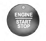
Keyless Starting
Note: The keyless starting system may not function if the key is close to metal objects or electronic devices such as cellular phones.
Note: A valid key must be located inside your vehicle to switch the ignition on and start the engine.
Ignition Modes