Lincoln Corsair: Automatic Transmission External Controls - 8-Speed Automatic Transmission – 8F35/8F40 / Description and Operation - External Controls - System Operation and Component Description
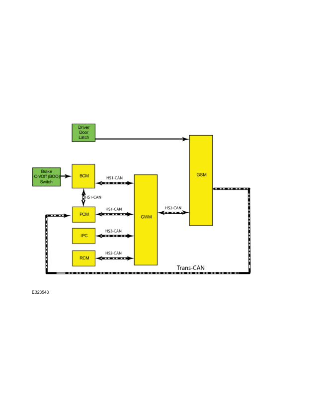
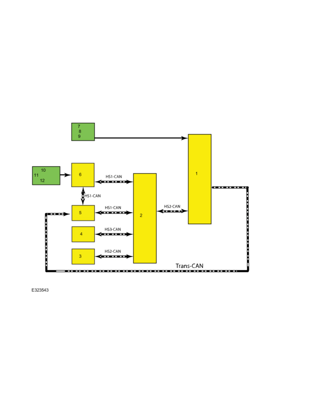
System Diagram
| Item | Description |
|---|---|
| 1 | GSM |
| 2 | GWM |
| 3 | RCM |
| 4 | IPC |
| 5 | PCM |
| 6 | BCM |
| 7 | Driver |
| 8 | Door |
| 9 | Latch |
| 10 | Brake |
| 11 | On/Off (BOO) |
| 12 | Switch |
Network Message Chart
| Broadcast Message | Originating Module | Message Purpose |
|---|---|---|
| Brake switch position | BCM | Input from brake switch necessary to change gears. |
| Gear data | GSM | Message sent to PCM which gear is commanded. |
| Gear confirmation | PCM | Input to GSM confirming gear selection. |
| PRND mode | IPC | Used for PRND display. |
| Gear command | PCM | Input to change gears. |
| Key in ignition status | BCM | Input used to change gears. |
| Vehicle lock status | BCM | Input used to move transmission out of P . |
| Seat belt buckle data | RCM | Input from seat belt buckle to determine driver presence. |
System Operation
Component Description
When the driver needs to change gear position the driver selects P R N D by pressing a GSM button. The GSM senses the position and sends a request over the Subnet Network, and the High Speed Controller Area Network 2 (HS2-CAN) through the GWM over the High Speed Controller Area Network 1 (HS1-CAN) to the PCM . The PCM receives the input from the GSM , combines in vehicle conditions and moves the transmission to the commanded position. The PCM reads the transmission range sensor (TRS) and confirms the correct position has been achieved.
GSM
Each GSM button has three individual switch contacts that are used as input that the button has been pressed. If one switch contact is seen as nonfunctional the system will still work properly. However, if two switch contacts fail the button is no longer deemed reliable and a fault message is displayed. When park is selected above 5 mph neutral is provided along with a message in the IPC . The Brake Transmission Shift Interlock (BTSI) CAN signal is used for normal function to shift from P .
RCM
The shift by wire system uses the driver’s safety belt buckle as one of several inputs used to determine driver presence. If the buckle is deemed faulted for any reason the system reads this as “unbuckled” so that any time the door transitions to “open” below a set speed the PCM commands a to return to park.
PCM
The PCM actuates the transmission in place of a conventional selector lever and selector lever cable. It receives commands from the GSM via High Speed CAN .
IPC
The IPC receives signals from the PCM and displays the current range of the transmission on the PRNDS. Under some circumstances messages from the shift by wire system are also displayed for the customer on the multifunction display. For example, "Press Brake to shift from Park" is displayed when an attempt to shift to a non-park GSM position while the vehicle is in P and the brake is not pressed.
BCM
The BCM provides Brake Transmission Shift Interlock (BTSI) information, GSM LED intensity status, electronic door lock commands, and ignition status to the GSM and PCM . The BCM is also responsible for customizing BTSI and other signals based on local regulations and vehicle features.
Push Button Shift Modes
Automatic Return to Park
NOTE: This feature does not operate when your vehicle is in Stay In Neutral Mode or neutral tow.
The vehicle has a safety feature that will automatically shift the transmission into P when one of the following conditions are met at low speed:
- The ignition is turned off and vehicle falls below low speed threshold
- The driver door is opened with the seat belt unlatched
- Unlatching the safety belt while the driver door is open
Stay in Neutral Mode
If necessary for the vehicle to stay in N without the driver present, such as being pulled through a car wash, this mode disables return to park. In stay in neutral the system will remain awake draining the battery if the engine is off. To enter stay in neutral mode, press the N button on the GSM . Then, if the driver presses the N button on the GSM again, the vehicle will enter stay in neutral mode. During this mode the N position on the GSM flashes continuously and the instrument cluster will display N as the selected gear. To exit the stay in N mode, apply the brakes and shift out of N .
If the battery discharges while in stay in neutral mode, the park lock pawl solenoid will release and transmission will return to park. Do not tow the vehicle in this mode.
Manual Park Release
Refer to: External Controls - System Operation and Component
Description (307-05A Automatic Transmission External Controls - 8-Speed
Automatic Transmission – 8F35/8F40, Description and Operation).
for information on moving the transmission into N with the engine off or with a vehicle that will not crank.
Return to Park
NOTE: This feature may not work properly if the door ajar switch is malfunctioning.
The vehicle will return to P when any of the following conditions are met:
- The vehicle is turned off.
- The vehicle is stopped and the driver door is open with the safety belt unlatched.
- The vehicle is stopped and the safety belt is unlatched with the driver door opened.
If the vehicle is turned off while moving, the transmission will first shift into N until it comes to a complete stop and then will shift into P automatically.
Park by Wire
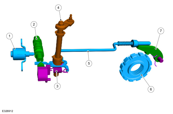
| Item | Description |
| 1 | Park lock solenoid |
| 2 | Park lock valve |
| 3 | Park return spring |
| 4 | Park override lever and shaft |
| 5 | Park pawl actuator rod |
| 6 | Park gear |
| 7 | Park pawl |
Park by Wire
- Uses a GSM with push buttons in place of a mechanical shifter as the customer interface for selecting (P, R, N, D).
-
The transmission hydraulic controls are modified
using a park lock pawl valve connected to the park rod which unlocks
and locks the parking pawl from the carrier.
- Uses clutch C and F hydraulic pressure to push the system out of P .
- Once out of P , line pressure can continue to hold the system out of P .
- A park lock pawl solenoid is used to allow the system to remain out of P when the engine is not running.
- The dual TR sensors indicate the state of the P system and are not used to determine customer selected range, which is now provided by the GSM .
Park Override
A mechanical P
override has been provided for in-plant use and towing. This consists
of a release cable that is accessed near the driver's knee bolster area,
normal operating position or park override position. In the override
position the park lock pawl valve is held in the applied position to
keep the parking pawl unlocked from the carrier.
Refer to:
Transmission Park by Wire Manual Release (307-05A Automatic Transmission
External Controls - 8-Speed Automatic Transmission – 8F35/8F40, General
Procedures).
 Description and Operation - External Controls - Overview
The shift by wire system uses a push button GSM to interface with the PCM to select gear positions.
The steering wheel includes paddle switches allowing the driver to
manually shift the transmission when D is selected on the GSM ...
 Diagnosis and Testing - External Controls
Diagnostic Trouble Code (DTC) Chart
Diagnostics in this manual assume a certain skill level and knowledge of Ford-specific diagnostic practices. REFER to: Diagnostic Methods (100-00 General Information, Description and Operation)...
Other information:
Lincoln Corsair 2020-2024 Service Manual: Removal and Installation - Power Fold Seat Motor
Removal NOTE: Removal steps in this procedure may contain installation details. Remove the rear seat cushion and cover as an assembly. Refer to: Rear Seat Cushion Cover (501-10B Rear Seats, Removal and Installation). Disconnect the power fold seat motor electrical connector...
Lincoln Corsair 2020-2024 Owners Manual: Getting the Services You Need
Warranty repairs to your vehicle must be performed by an authorized dealer. While any authorized dealer handling your vehicle line provides warranty service, we recommend you return to your selling authorized dealer who wants to ensure your continued satisfaction...
Categories
- Manuals Home
- 1st Generation Lincoln Corsair Owners Manual
- 1st Generation Lincoln Corsair Service Manual
- Programming the Garage Door Opener to Your Garage Door Opener Motor
- Opening and Closing the Hood
- Selecting a Drive Mode. DRIVE MODES
- New on site
- Most important about car
Selecting a Drive Mode. DRIVE MODES
Selecting a Drive Mode
Note: Drive mode changes may not be available when the ignition is off.