Lincoln Corsair: Front End Sheet Metal Repairs / Removal and Installation - Front Side Member
Special Tool(s) / General Equipment
| Resistance Spotwelding Equipment | |
| 8 mm Drill Bit | |
| MIG/MAG Welding Equipment | |
| Spot Weld Drill Bit | |
| Locking Pliers |
Removal
.jpg) WARNING:
Electric vehicles damaged by a crash may have compromised
high voltage safety systems and present a potential high voltage
electrical shock hazard. Exercise caution and wear appropriate Personal
Protective Equipment (PPE) safety gear, including high voltage safety
gloves and boots. Remove all metallic jewelry, including watches and
rings. Isolate the HV system as directed by the Ford Emergency Response
Guide for the vehicle. Failure to follow these instructions may result
in serious personal injury or death.
WARNING:
Electric vehicles damaged by a crash may have compromised
high voltage safety systems and present a potential high voltage
electrical shock hazard. Exercise caution and wear appropriate Personal
Protective Equipment (PPE) safety gear, including high voltage safety
gloves and boots. Remove all metallic jewelry, including watches and
rings. Isolate the HV system as directed by the Ford Emergency Response
Guide for the vehicle. Failure to follow these instructions may result
in serious personal injury or death.
NOTICE: Battery electric vehicle (BEV), hybrid electric vehicle (HEV) and plug-in hybrid electric vehicle (PHEV) contain a high-voltage battery. Before cutting or welding near the high-voltage battery it must be removed to avoid damage.
NOTE: Left hand (LH) side shown, right hand (RH) side similar.
-
Refer to: Health and Safety Precautions (100-00 General Information, Description and Operation).
WARNING:
Before beginning any service procedure in this
manual, refer to health and safety warnings in section 100-00 General
Information. Failure to follow this instruction may result in serious
personal injury.
Refer to: High Voltage System Health and Safety Precautions - Overview (100-00 General Information, Description and Operation).
-
Restore the vehicle to manufacturer's dimensions as required.
Refer to: Body and Frame (501-26 Body Repairs - Vehicle Specific Information and Tolerance Checks, Description and Operation).
- Remove the battery tray LH side only.
-
Remove the fender apron panel reinforcement.
Refer to: Fender Apron Panel Reinforcement (501-27 Front End Sheet Metal Repairs, Removal and Installation).
-
NOTE: Support the subframe prior to removing the bolt.
Remove the bolt.
Refer to: Front Side Member (501-27 Front End Sheet Metal Repairs, Removal and Installation).
.jpg) |
-
Remove the welds.
Use the General Equipment: Spot Weld Drill Bit
.jpg) |
-
Remove the welds.
Use the General Equipment: Spot Weld Drill Bit
.jpg) |
-
Remove the front side member.
.jpg) |
Installation
WARNING:
Electric vehicles damaged by a crash may have compromised
high voltage safety systems and present a potential high voltage
electrical shock hazard. Exercise caution and wear appropriate Personal
Protective Equipment (PPE) safety gear, including high voltage safety
gloves and boots. Remove all metallic jewelry, including watches and
rings. Isolate the HV system as directed by the Ford Emergency Response
Guide for the vehicle. Failure to follow these instructions may result
in serious personal injury or death.
NOTICE: Battery electric vehicle (BEV), hybrid electric vehicle (HEV) and plug-in hybrid electric vehicle (PHEV) contain a high-voltage battery. Before cutting or welding near the high-voltage battery it must be removed to avoid damage.
NOTICE: The high-voltage battery in a battery electric vehicle (BEV), hybrid electric vehicle (HEV) or plug-in hybrid electric vehicle (PHEV) can be affected and damaged by excessively high temperatures. The temperature in some body shop paint booths can exceed 60° C (140° F). Therefore, during refinishing operations, the paint booth temperature must set at or below 60° C (140° F) with a bake time of 45 minutes or less. Temperatures in excess of 60° C (140° F) or bake durations longer than 45 minutes will require the high-voltage battery be removed from the vehicle prior to placing in the paint booth.
NOTICE: If refinishing cure temperatures exceed 60° C (140° F), the charge port light ring on plug-in vehicles must be removed.
NOTE: Factory welds may be substituted with resistance or metal inert gas (MIG) plug welds. Resistance welds may not be placed directly over original location. They must be placed adjacent to original location and match factory welds in quantity. Metal inert gas (MIG) plug welds must equal factory welds in both location and quantity.
NOTE: Left hand (LH) side shown, right hand (RH) side similar.
-
Refer to: Health and Safety Precautions (100-00 General Information, Description and Operation).
WARNING:
Before beginning any service procedure in this
manual, refer to health and safety warnings in section 100-00 General
Information. Failure to follow this instruction may result in serious
personal injury.
Refer to: High Voltage System Health and Safety Precautions - Overview (100-00 General Information, Description and Operation).
-
Drill holes for plug welding.
Use the General Equipment: 8 mm Drill Bit
.jpg) |
-
Install, properly position and clamp the front side member.
Use the General Equipment: Locking Pliers
.jpg) |
-
Install the welds.
Use the General Equipment: Resistance Spotwelding Equipment
.jpg) |
-
Install the welds.
Use the General Equipment: MIG/MAG Welding Equipment
.jpg) |
-
Install the fender apron panel reinforcement.
Refer to: Fender Apron Panel Reinforcement (501-27 Front End Sheet Metal Repairs, Removal and Installation).
-
Install the the battery tray LH side only.
-
Install the subframe bolt.
Torque: 129 lb.ft (175 Nm)
|

 Removal and Installation - Front Side Member Section
Special Tool(s) /
General Equipment
Resistance Spotwelding Equipment
Spherical Cutter
Air Body Saw
MIG/MAG Welding Equipment
Spot Weld Drill Bit
Locking Pliers
Removal
WARNING:
Electric vehicles damaged by a crash may have compromised
high voltage safety systems and present a potential high voltage
electrical shock hazard...
Other information:
Lincoln Corsair 2020-2026 Service Manual: Description and Operation - Turbocharger - Component Location
2.0L EcoBoost Item Description 1 Turbocharger 2 Turbocharger oil supply tube 3 Turbocharger coolant supply tube 4 Turbocharger oil return tube 5 Turbocharger coolant return tube ..
Lincoln Corsair 2020-2026 Owners Manual: Entering a Perpendicular Parking Space
Press the active park assist button.Note: Active park assist does not recognize parking space lines and centers your vehicle between objects. Press the active park assist icon on the touchscreen. Select perpendicular parking. Use the turn signal lever to search for a parking space on the driver or passenger side of your vehicle.Note: If you do not use the turn signal lever, the ..
Categories
- Manuals Home
- 1st Generation Lincoln Corsair Owners Manual
- 1st Generation Lincoln Corsair Service Manual
- Selecting a Drive Mode. DRIVE MODES
- Child Safety Locks
- Programming the Garage Door Opener to Your Garage Door Opener Motor
- New on site
- Most important about car
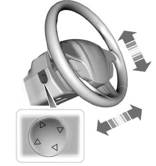
Adjusting the Steering Wheel - Vehicles With: Power Adjustable Steering Column
WARNING: Do not adjust the steering wheel when your vehicle is moving.
Note: Make sure that you are sitting in the correct position.