Lincoln Corsair: Front End Sheet Metal Repairs / Removal and Installation - Front Side Member Section
Special Tool(s) /
General Equipment
| Resistance Spotwelding Equipment |
| Spherical Cutter |
| Air Body Saw |
| MIG/MAG Welding Equipment |
| Spot Weld Drill Bit |
| Locking Pliers |
Removal
.jpg) WARNING:
Electric vehicles damaged by a crash may have compromised
high voltage safety systems and present a potential high voltage
electrical shock hazard. Exercise caution and wear appropriate Personal
Protective Equipment (PPE) safety gear, including high voltage safety
gloves and boots. Remove all metallic jewelry, including watches and
rings. Isolate the HV system as directed by the Ford Emergency Response
Guide for the vehicle. Failure to follow these instructions may result
in serious personal injury or death.
WARNING:
Electric vehicles damaged by a crash may have compromised
high voltage safety systems and present a potential high voltage
electrical shock hazard. Exercise caution and wear appropriate Personal
Protective Equipment (PPE) safety gear, including high voltage safety
gloves and boots. Remove all metallic jewelry, including watches and
rings. Isolate the HV system as directed by the Ford Emergency Response
Guide for the vehicle. Failure to follow these instructions may result
in serious personal injury or death.
NOTICE:
BEV (Battery Electric Vehicle), HEV (Hybrid Electric
Vehicle) and PHEV (plug-in hybrid electric vehicle) contain a HVB (High
Voltage Battery). Before welding near the HVB, the HVB must be removed
to avoid heat damage.
NOTE:
Left hand side shown, right hand side similar.
NOTE:
The front side member is constructed from a tailor welded
blank. No sectioning may occur at the laser weld line. If damage extends
rearward of the laser line, the entire frame member must be replaced at
factory seams.
-
WARNING:
Before beginning any service procedure in this
manual, refer to health and safety warnings in section 100-00 General
Information. Failure to follow this instruction may result in serious
personal injury.
Refer to: Health and Safety Precautions (100-00 General Information, Description and Operation).
Refer to: High Voltage System Health and Safety Precautions - Overview (100-00 General Information, Description and Operation).
-
Depower the SRS .
Refer to: Supplemental Restraint System (SRS) Depowering (501-20B Supplemental Restraint System, General Procedures).
-
Restore the vehicle to manufacturer's dimensions as required.
Refer to: Body and Frame (501-26 Body Repairs - Vehicle Specific Information and Tolerance Checks, Description and Operation).
-
Remove the front bumper.
Refer to: Front Bumper (501-19 Bumpers, Removal and Installation).
-
Remove the hood.
Refer to: Hood (501-02 Front End Body Panels, Removal and Installation).
-
Remove the fender and fender splash shield.
Refer to: Fender (501-02 Front End Body Panels, Removal and Installation).
Refer to: Fender Splash Shield (501-02 Front End Body Panels, Removal and Installation).
-
Remove the cooling module.
Refer to: Cooling Module (303-03A Engine Cooling - 2.0L EcoBoost (177kW/240PS) – MI4, Removal and Installation).
Refer to: Cooling Module (303-03B Engine Cooling - 2.3L EcoBoost (199kW/270PS), Removal and Installation).
-
Remove the welds.
Use the General Equipment: Spot Weld Drill Bit
-
Remove the welds.
Use the General Equipment: Spot Weld Drill Bit
-
Remove the bumper bracket.
-
Remove the welds.
Use the General Equipment: Spot Weld Drill Bit
-
Remove the bolts.
-
Remove the bolts.
-
Carefully measure 50 mm forward from the laser weld line and cut the inner frame member.
Use the General Equipment: Air Body Saw
Use the General Equipment: Spherical Cutter
-
Remove the welds.
Use the General Equipment: Spot Weld Drill Bit
-
Remove the inner side member section.
Use the General Equipment: Spot Weld Drill Bit
-
Carefully measure as indicated and cut the outer side frame member.
Use the General Equipment: Air Body Saw
Use the General Equipment: Spherical Cutter
-
Remove the welds.
Use the General Equipment: Spot Weld Drill Bit
-
Remove the inner side member section.
Use the General Equipment: Spot Weld Drill Bit
Installation
WARNING:
Electric vehicles damaged by a crash may have compromised
high voltage safety systems and present a potential high voltage
electrical shock hazard. Exercise caution and wear appropriate Personal
Protective Equipment (PPE) safety gear, including high voltage safety
gloves and boots. Remove all metallic jewelry, including watches and
rings. Isolate the HV system as directed by the Ford Emergency Response
Guide for the vehicle. Failure to follow these instructions may result
in serious personal injury or death.
NOTICE:
The high-voltage battery in a BEV (Battery Electric
Vehicle), HEV (Hybrid Electric Vehicle) or PHEV (Plug-In Hybrid Electric
Vehicle) can be affected and damaged by excessively high temperatures.
The temperature in some body shop paint booths can exceed 60° C (140°
F). Therefore, during refinishing operations, the paint booth
temperature must set at or below 60° C (140° F) with a bake time of 45
minutes or less. Temperatures in excess of 60° C (140° F) or bake
durations longer than 45 minutes will require the high-voltage battery
be removed from the vehicle prior to placing in the paint booth.
NOTICE:
EV (Electric Vehicle), HEV (Hybrid Electric Vehicle) and
PHEV (Plug-In Hybrid Electric Vehicle) vehicles contain a HVB (High
Voltage Battery). Before welding near the HVB, the HVB must be removed
to avoid heat damage.
NOTICE:
If refinishing cure temperatures exceed 60°C (140°F), the charge port light ring must be removed.
NOTE:
Factory welds may be replaced with resistance spot welds or
MIG (metal inert gas) plug welds. Resistance spot welds may not be
placed directly over original location. They must be placed adjacent to
original location and equal factory welds in quantity. MIG (metal inert
gas) plug welds must equal factory welds in both location and quantity
NOTE:
Left hand (LH) side shown, right hand (RH) side similar.
-
WARNING:
Before beginning any service procedure in this
manual, refer to health and safety warnings in section 100-00 General
Information. Failure to follow this instruction may result in serious
personal injury.
Refer to: Health and Safety Precautions (100-00 General Information, Description and Operation).
Refer to: High Voltage System Health and Safety Precautions - Overview (100-00 General Information, Description and Operation).
-
Cut the service part to fit the repair area.
Use the General Equipment: Air Body Saw
Use the General Equipment: Spherical Cutter
-
Install, properly position and clamp the inner side member section.
Use the General Equipment: Locking Pliers
-
NOTE:
The use of a backer plate in welding is recommended.
Completely seam weld the sectioning joint.
Use the General Equipment: MIG/MAG Welding Equipment
-
Cut the service part to fit the repair area.
Use the General Equipment: Air Body Saw
Use the General Equipment: Spherical Cutter
-
Install, properly position and clamp the outer side member section.
Use the General Equipment: Locking Pliers
-
NOTE:
The use of a backer plate in welding is recommended.
Completely seam weld the sectioning joint.
Use the General Equipment: MIG/MAG Welding Equipment
-
Dress all welds using typical metal finishing techniques and materials.
-
Install the welds.
-
Install, properly position and clamp the bumper bracket.
Use the General Equipment: Locking Pliers
-
Install the welds.
Use the General Equipment: Resistance Spotwelding Equipment
-
Install the welds.
Use the General Equipment: Resistance Spotwelding Equipment
-
Install the welds.
Use the General Equipment: Resistance Spotwelding Equipment
-
Install the bolts.
Torque:
18 lb.ft (25 Nm)
-
Install the bolts.
Torque:
18 lb.ft (25 Nm)
-
Refinish the entire repair using a Ford approved paint system.
-
Restore corrosion protection.
Refer to: Corrosion Prevention (501-25 Body Repairs - General Information, General Procedures).
-
Install the cooling module.
Refer to: Cooling Module (303-03A Engine Cooling - 2.0L EcoBoost (177kW/240PS) – MI4, Removal and Installation).
Refer to: Cooling Module (303-03B Engine Cooling - 2.3L EcoBoost (199kW/270PS), Removal and Installation).
-
Install the fender and fender splash shield.
Refer to: Fender (501-02 Front End Body Panels, Removal and Installation).
Refer to: Fender Splash Shield (501-02 Front End Body Panels, Removal and Installation).
-
Install the hood.
Refer to: Hood (501-02 Front End Body Panels, Removal and Installation).
-
Install the front bumper.
Refer to: Front Bumper (501-19 Bumpers, Removal and Installation).
-
Repower the SRS .
Refer to: Supplemental Restraint System (SRS) Repowering (501-20B Supplemental Restraint System, General Procedures).
Special Tool(s) /
General Equipment
Resistance Spotwelding Equipment
8 mm Drill Bit
MIG/MAG Welding Equipment
Spot Weld Drill Bit
Locking Pliers
Removal
WARNING:
Electric vehicles damaged by a crash may have compromised
high voltage safety systems and present a potential high voltage
electrical shock hazard...
Other information:
Emergency Towing
In the event your vehicle becomes disabled
(without access to wheel dollies, car-hauling
trailer, or flatbed transport vehicle), it can be
flat-towed (all wheels on the ground,
regardless of the powertrain/transmission
configuration) under the following conditions:
The vehicle is facing forward so that it is
towed in a forward direction.
Shift the transmission into neutr..
Materials
Name
Specification
Motorcraft® Premium Windshield Wash Concentrate with BitterantZC-32-B2
WSS-M14P19-A
Removal
Remove the windshield washer reservoir.
Refer to: Windshield Washer Reservoir (501-16 Wipers and Washers, Removal and Installation).
Disconnect the electrical connector.
NOTE:
Be prepared to collect escaping flui..
Categories
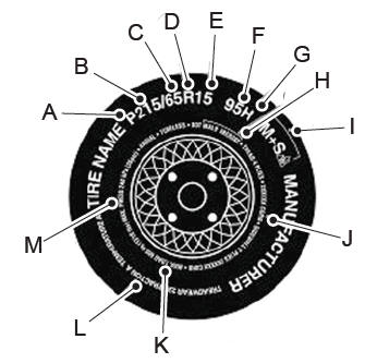
P215/65R15 95H is an example of a tire
size, load index and speed rating. The
definitions of these items are listed
below. (Note that the tire size, load index
and speed rating for your vehicle may
be different from this example.)
P: Indicates a tire, designated by the
Tire and Rim Association, that may be
used for service on cars, sport utility
vehicles, minivans and light trucks. Note:
If your tire size does not begin with a
letter this may mean it is designated by
either the European Tire and Rim
Technical Organization or the Japan Tire
Manufacturing Association.
215: Indicates the nominal width of
the tire in millimeters from sidewall edge
to sidewall edge. In general, the larger
the number, the wider the tire.
65: Indicates the aspect ratio which
gives the tire's ratio of height to width.
R: Indicates a radial type tire.
15: Indicates the wheel or rim
diameter in inches. If you change your
wheel size, you will have to purchase
new tires to match the new wheel
diameter.
95: Indicates the tire's load index. It
is an index that relates to how much
weight a tire can carry. You may find this
information in your owner’s manual. If
not, contact a local tire dealer.
read more
.jpg)
.jpg)
.jpg)
.jpg)
.jpg)
.jpg)
.jpg)
.jpg)
.jpg)
.jpg)
.jpg)
.jpg)
.jpg)
.jpg)
.jpg)
.jpg)
.jpg)
.jpg)
.jpg)
.jpg)
.jpg)
.jpg)
.jpg)
 Removal and Installation - Front Side Member