Lincoln Corsair: Engine - 2.0L EcoBoost (177kW/240PS) – MI4 / Removal and Installation - Crankshaft Pulley
Special Tool(s) / General Equipment
 |
303-1521 Alignment Tool, Crankshaft Position Sensor TKIT-2010C-FLM |
 |
303-1686 Holding Tool, Camshaft |
 |
303-1689 Holding Tool, Crank Damper |
 |
303-507 Timing Peg, Crankshaft TDC TKIT-2001N-FLM TKIT-2001N-ROW |
Removal
LHD AWD/LHD FWD
NOTICE: Do not loosen or remove the crankshaft pulley bolt without first installing the special tools as instructed in this procedure. The crankshaft pulley and the crankshaft timing sprocket are not keyed to the crankshaft. The crankshaft, the crankshaft sprocket and the pulley are fitted together by friction. For that reason, the crankshaft sprocket is also unfastened if the pulley bolt is loosened. Before any repair requiring loosening or removal of the crankshaft pulley bolt, the crankshaft and camshafts must be locked in place by the special service tools, otherwise severe engine damage can occur.
NOTICE: During engine repair procedures, cleanliness is extremely important. All parts must be thoroughly cleaned and any foreign material, including any material created while cleaning gasket surfaces, that enters the oil passages, coolant passages or the oil pan, can cause engine failure.
-
With the vehicle in NEUTRAL, position it on a hoist.
Refer to: Jacking and Lifting - Overview (100-02 Jacking and Lifting, Description and Operation).
-
Remove the retainers and the underbody shield.
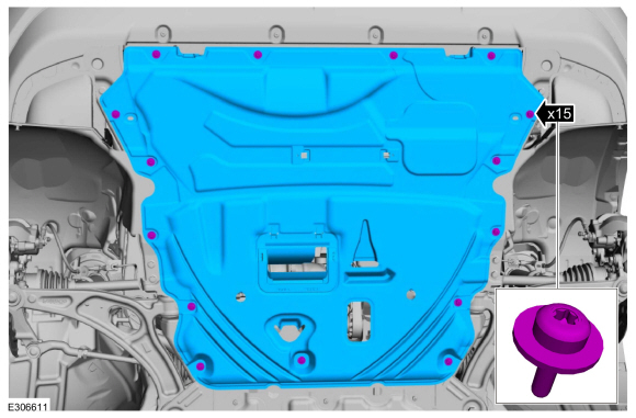 |
-
Remove the RH fender splash shield.
Refer to: Fender Splash Shield (501-02 Front End Body Panels, Removal and Installation).
LHD AWD
-
Remove the AWD RH halfshaft.
Refer to: Front Halfshaft RH - AWD (205-04 Front Drive Halfshafts, Removal and Installation).
-
Remove the bolts and the transfer case support bracket.
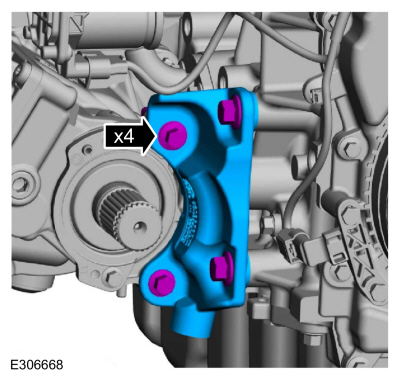 |
LHD FWD
-
Remove the FWD RH halfshaft.
Refer to: Front Halfshaft RH - 2.0L EcoBoost (177kW/240PS) – MI4, FWD (205-04 Front Drive Halfshafts, Removal and Installation).
-
Remove the bolts and the halfshaft support bracket.
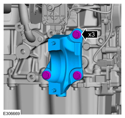 |
LHD AWD/LHD FWD
-
Remove the accessory drive belt.
Refer to: Accessory Drive Belt (303-05B Accessory Drive - 2.3L EcoBoost (199kW/270PS), Removal and Installation).
-
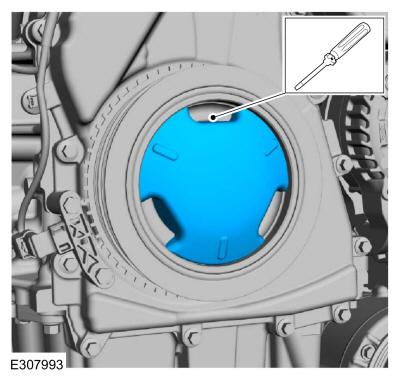
If equipped, release the tabs and remove the crankshaft pulley cover.
 |
-
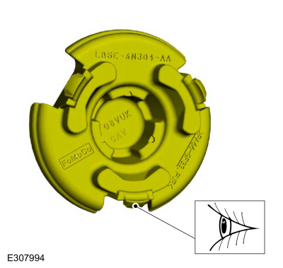
If equipped, inspect the 3 crankshaft pulley cover
tabs for damage, if damaged replace the crankshaft pulley cover.
 |
-
-
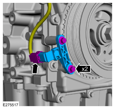
Disconnect the CKP sensor electrical connector.
-
Remove the bolts and the CKP sensor.
-
Disconnect the CKP sensor electrical connector.
 |
-
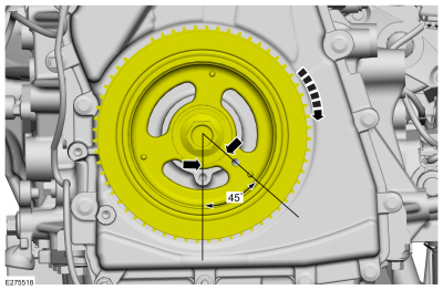
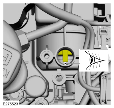
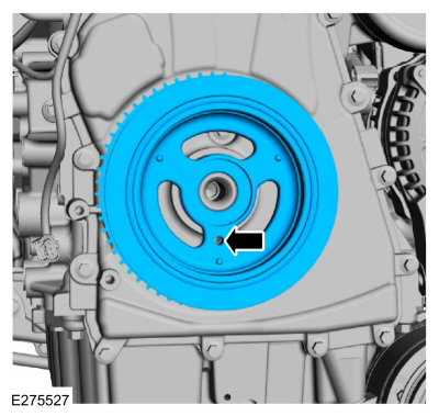
Turn the crankshaft clockwise until the No.1 piston is 45 degrees BTDC
using the guide holes on the engine front cover and the crankshaft
pulley.
 |
-
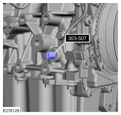
Remove the engine plug bolt.
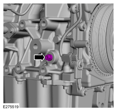 |
- Install Special Service Tool: 303-507 Timing Peg, Crankshaft TDC.
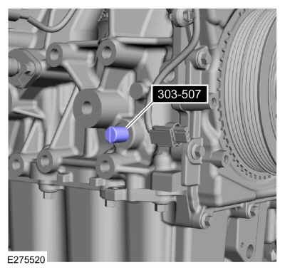 |
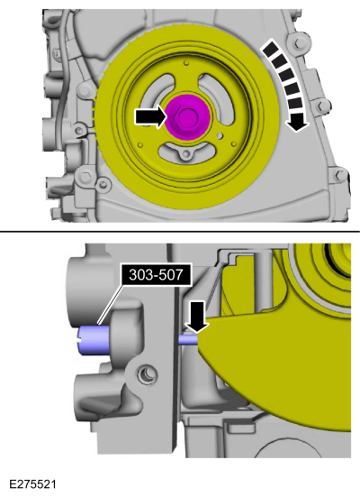
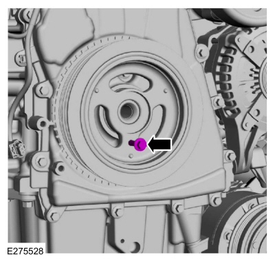
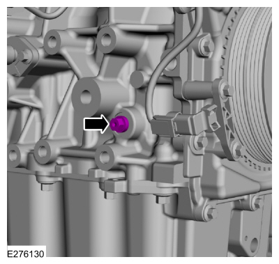
-
NOTE: The Crankshaft TDC Timing Peg will contact the crankshaft and prevent it from turning past TDC . However, the crankshaft can still be rotated in the counterclockwise direction. The crankshaft must remain at the TDC position during the crankshaft pulley removal and installation.
NOTE: The engine front cover is removed from graphic for clarity.
Rotate the crankshaft clockwise until the contacts the special tool.
Use Special Service Tool: 303-507 Timing Peg, Crankshaft TDC.
 |
-
Remove the RH and LH CMP sensors.
Refer to: Camshaft Position (CMP) Sensor (303-14A Electronic Engine Controls - 2.0L EcoBoost (177kW/240PS) – MI4, Removal and Installation).
-
NOTE: Exhaust camshaft shown, intake camshaft similar.
Make sure the camshaft trigger wheels are aligned as shown.
 |
-
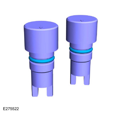
NOTE: Removing the O-ring seals will aid in the installation of 303-1686.
Remove the O-ring seals from 303-1686.
 |
-
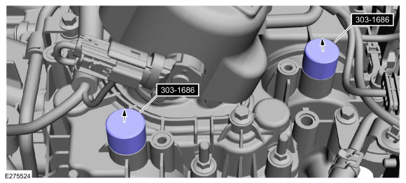
NOTICE: The Camshaft Alignment Tool is for camshaft alignment only. Using this tool to prevent engine rotation can result in engine damage.
NOTICE: Do not force the camshaft holding tool into the valve cover or damage can result to the camshaft trigger wheels.
NOTE: The camshaft trigger wheels are offset. If the Camshaft Holding Tools cannot be installed, remove the TDC Timing Peg and rotate the crankshaft three-fourths of a revolution clockwise and repeat steps 10 and 11 of this removal procedure.
Install Special Service Tool: 303-1686 Holding Tool, Camshaft.
 |
-
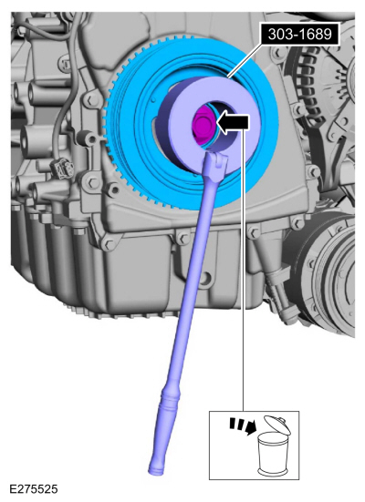
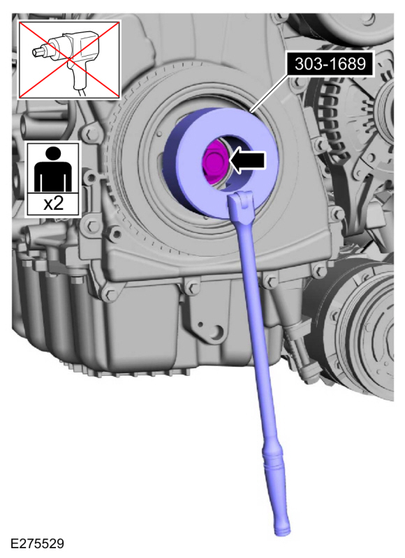
NOTICE: The crankshaft must remain in the TDC position during removal of the pulley bolt or damage to the engine can occur. Therefore, the crankshaft pulley must be held in place with the Crank Damper Holding Tool and the bolt should be removed using an air impact wrench (1/2-in drive minimum).
-
Using the special tool, remove the bolt, washer and the crankshaft pulley.
Use Special Service Tool: 303-1689 Holding Tool, Crank Damper.
-
NOTE: If necessary, retain the original crankshaft pulley bolt to use for the removal of the crankshaft front seal.
Discard the bolt.
-
Using the special tool, remove the bolt, washer and the crankshaft pulley.
 |
Installation
LHD AWD/LHD FWD
-
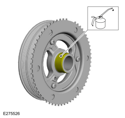
Lubricate the crankshaft pulley with clean engine oil.
 |
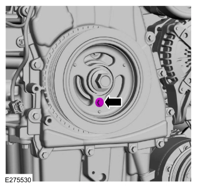
-
Position the crankshaft pulley onto the crankshaft with the access hole at the 6 o'clock position.
 |
-
NOTE: This step will correctly align the crankshaft pulley to the crankshaft.
Install an M6 bolt.
 |
-
NOTICE: The crankshaft must remain in the TDC position during installation of the pulley bolt or damage to the engine can occur. Therefore, the crankshaft pulley must be held in place with the Crank Damper Holding Tool and the bolt should be installed using hand tools only.
Using the special tool, install the new crankshaft bolt and washer and tighten.
Use Special Service Tool: 303-1689 Holding Tool, Crank Damper.
Torque:
Stage 1: 74 lb.ft (100 Nm)
Stage 2: 90°
 |
-
Remove the M6 bolt.
 |
-
NOTE: Do not tighten the CKP sensor bolts at this time.
Install the CKP sensor and the bolts finger tight.
 |
-
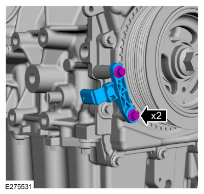
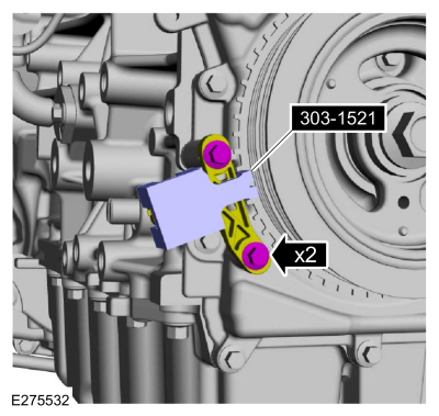
Install the special tool onto the CKP sensor and the tooth of the crankshaft pulley trigger wheel.
Use Special Service Tool: 303-1521 Alignment Tool, Crankshaft Position Sensor.
Torque: 97 lb.in (11 Nm)
 |
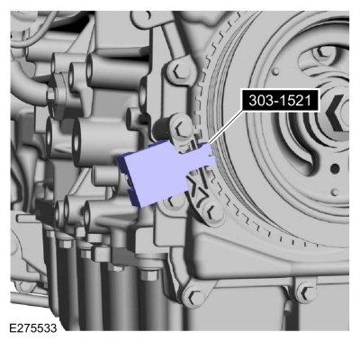
- Remove Special Service Tool: 303-1521 Alignment Tool, Crankshaft Position Sensor.
 |
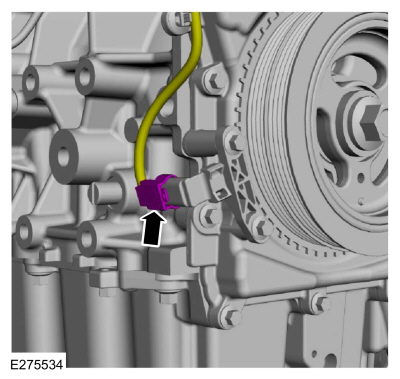
-
Connect the CKP sensor electrical connector.
 |
-
NOTICE: Do not rotate the crankshaft until the special tools 303-1686 are removed from the valve cover.
Remove Special Service Tool: 303-507 Timing Peg, Crankshaft TDC.
 |
-
Install the engine plug bolt.
Torque: 177 lb.in (20 Nm)
 |
-
If equipped.
-
Align and insert 2 tabs of the crankshaft pulley
cover into the open spaces between the ribs of the crankcase pulley.
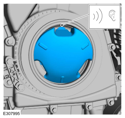
-
Press the third tab firmly into position until a snap is heard or felt.
-
Verify that the crankshaft pulley cover is securely in place.
-
Align and insert 2 tabs of the crankshaft pulley
cover into the open spaces between the ribs of the crankcase pulley.
 |
- Remove Special Service Tool: 303-1686 Holding Tool, Camshaft.
|
-
Install the O-ring seals on 303-1686.
|
-
Install the following items:
-
Install the RH and LH CMP sensors.
Refer to: Camshaft Position (CMP) Sensor (303-14A Electronic Engine Controls - 2.0L EcoBoost (177kW/240PS) – MI4, Removal and Installation).
-
Install the accessory drive belt.
Refer to: Accessory Drive Belt (303-05B Accessory Drive - 2.3L EcoBoost (199kW/270PS), Removal and Installation).
-
Install the RH and LH CMP sensors.
LHD FWD
-
Install the halfshaft support bracket and the bolts.
Torque: 35 lb.ft (48 Nm)
|
-
Install the FWD RH halfshaft.
Refer to: Front Halfshaft RH - 2.0L EcoBoost (177kW/240PS) – MI4, FWD (205-04 Front Drive Halfshafts, Removal and Installation).
LHD AWD
-
Install the transfer case support bracket and the bolts.
Torque: 35 lb.ft (48 Nm)
|
-
Install the AWD RH halfshaft.
Refer to: Front Halfshaft RH - AWD (205-04 Front Drive Halfshafts, Removal and Installation).
LHD AWD/LHD FWD
-
Install the RH fender splash shield.
Refer to: Fender Splash Shield (501-02 Front End Body Panels, Removal and Installation).
-
Install the underbody shield and the retainers.
Torque: 13 lb.in (1.5 Nm)
|
-
Use the Powertrain Control Module (PCM) Misfire
Monitor Profile Correction routine in the diagnostic scan tool.
 Removal and Installation - Crankshaft Front Seal
Special Tool(s) /
General Equipment
303-096
(T74P-6150-A)
Installer, Camshaft Front Oil SealTKIT-2009TC-F
303-409
(T92C-6700-CH)
Remover, Crankshaft SealTKIT-1992-FH/FMH/FLMHTKIT-1993-LMH/MH
Removal
NOTICE:
During engine repair procedures, cleanliness is extremely
important...
 Removal and Installation - Crankshaft Rear Seal
Special Tool(s) /
General Equipment
303-328
(T88P-6701-B1)
Replacer, Rear SealTKIT-1988-FLMTKIT-1988-FTKIT-1988-LM
Oil Drain Equipment
Materials
Name
Specification
Motorcraft® High Performance Engine RTV SiliconeTA-357
WSE-M4G323-A6
Removal
Remove the flexplate...
Other information:
Lincoln Corsair 2020-2026 Service Manual: Removal and Installation - Transmission Park Manual Release Cable
Removal Remove the battery tray. Refer to: Battery Tray - 2.0L EcoBoost (177kW/240PS) – MI4/2.3L EcoBoost (199kW/270PS) (414-01 Battery, Mounting and Cables, Removal and Installation). Disconnect the upper park manual release cable from the lever...
Lincoln Corsair 2020-2026 Owners Manual: Safety Precautions
WARNING: Do not overfill the fuel tank. The pressure in an overfilled tank may cause leakage and lead to fuel spray and fire. WARNING: The fuel system may be under pressure. If you hear a hissing sound near the fuel filler inlet, do not refuel until the sound stops...
Categories
- Manuals Home
- 1st Generation Lincoln Corsair Owners Manual
- 1st Generation Lincoln Corsair Service Manual
- Child Safety Locks
- Warning Lamps and Indicators
- Automatic Transmission - 8-Speed Automatic Transmission – 8F35/8F40
- New on site
- Most important about car
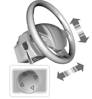
Adjusting the Steering Wheel - Vehicles With: Power Adjustable Steering Column
WARNING: Do not adjust the steering wheel when your vehicle is moving.
Note: Make sure that you are sitting in the correct position.