Lincoln Corsair: Electronic Engine Controls - 2.0L EcoBoost (177kW/240PS) – MI4 / Removal and Installation - Crankshaft Position (CKP) Sensor
Special Tool(s) / General Equipment
 |
303-1521 Alignment Tool, Crankshaft Position Sensor TKIT-2010C-FLM |
 |
303-507 Timing Peg, Crankshaft TDC TKIT-2001N-FLM TKIT-2001N-ROW |
Removal
All Vehicles
NOTE: Do not loosen or remove the crankshaft pulley bolt without first installing the special tools as instructed in this procedure. The crankshaft pulley and the crankshaft timing sprocket are not keyed to the crankshaft. The crankshaft, the crankshaft sprocket and the pulley are fitted together by friction, using diamond washers between the flange faces on each part. For that reason, the crankshaft sprocket is also unfastened if the pulley bolt is loosened. Before any repair requiring loosening or removal of the crankshaft pulley bolt, the crankshaft and camshafts must be locked in place by the special service tools, otherwise severe engine damage can occur.
NOTE: During engine repair procedures, cleanliness is extremely important. Any foreign material (including any material created while cleaning gasket surfaces) that enters the oil passages, coolant passages or the oil pan can cause engine failure.
-
With the vehicle in NEUTRAL, position it on a hoist.
Refer to: Jacking and Lifting - Overview (100-02 Jacking and Lifting, Description and Operation).
-
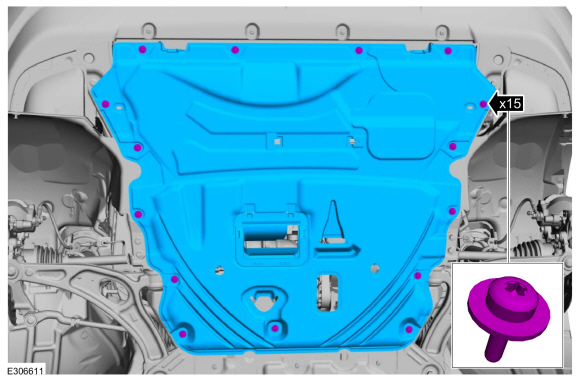
Remove the retainers and the underbody shield.
 |
AWD
-
Remove the RH fender splash shield.
Refer to: Fender Splash Shield (501-02 Front End Body Panels, Removal and Installation).
-
Remove the RH front halfshaft.
Refer to: Front Halfshaft RH - 2.0L EcoBoost (177kW/240PS) – MI4, FWD (205-04 Front Drive Halfshafts, Removal and Installation).
-
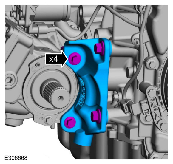
Remove the bolts and the transfer case support bracket.
 |
All Vehicles
-
-
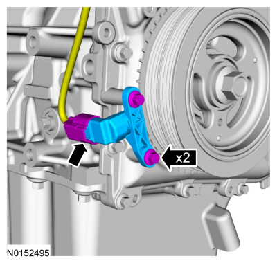
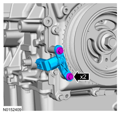
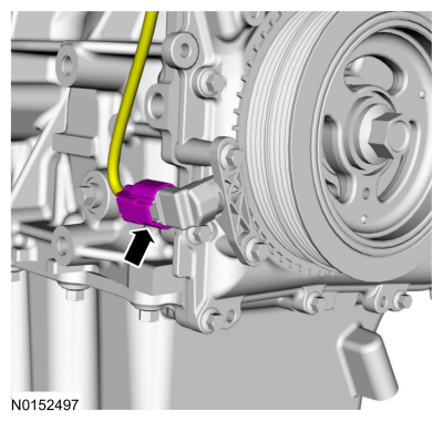
Disconnect the CKP sensor electrical connector.
-
Remove the 2 bolts and the CKP sensor.
-
Disconnect the CKP sensor electrical connector.
 |
Installation
All Vehicles
-
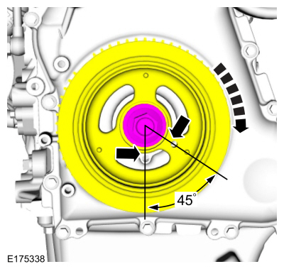
Turn the crankshaft clockwise until the No.1 piston is 45 degrees BTDC
using the guide holes on the engine front cover and the crankshaft
pulley.
 |
-
Remove the engine plug bolt.
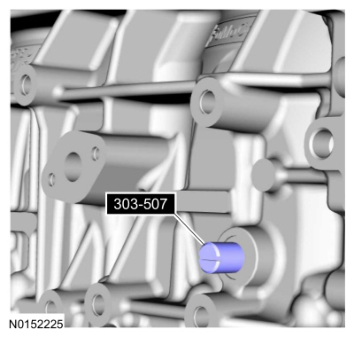
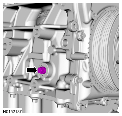 |
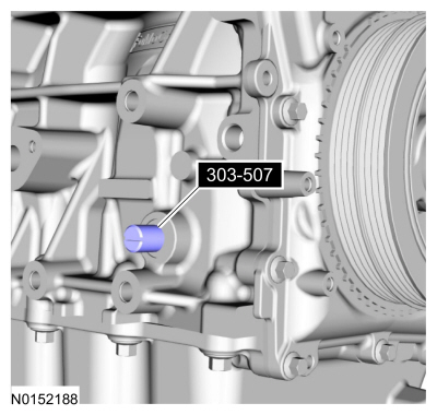
- Install Special Service Tool: 303-507 Timing Peg, Crankshaft TDC.
 |
-
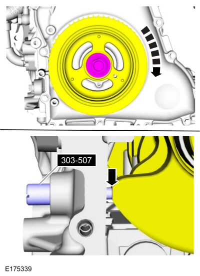
NOTE: The Crankshaft TDC Timing Peg will contact the crankshaft and prevent it from turning past TDC . However, the crankshaft can still be rotated in the counterclockwise direction. The crankshaft must remain at the TDC position during the crankshaft pulley removal and installation.
NOTE: The engine front cover is removed from graphic for clarity.
Rotate the crankshaft clockwise until the contacts the special tool.
Use Special Service Tool: 303-507 Timing Peg, Crankshaft TDC.
 |
-
NOTE: Do not tighten the CKP sensor bolts at this time.
Install the CKP sensor and the bolts.
 |
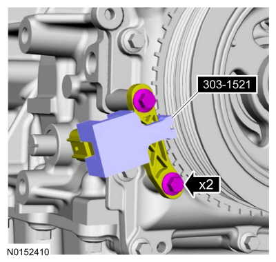
-
Install the Special Tool onto the CKP sensor and the tooth of the crankshaft pulley trigger wheel. Tighten CKP sensor bolts.
Use Special Service Tool: 303-1521 Alignment Tool, Crankshaft Position Sensor.
Torque: 97 lb.in (11 Nm)
 |
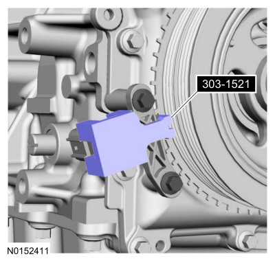
-
Remove the special service tool.
Use Special Service Tool: 303-1521 Alignment Tool, Crankshaft Position Sensor.
Remove Suggested Tool: 303-1521 Alignment Tool, Crankshaft Position Sensor.
 |
-
Remove special service tool.
Use Special Service Tool: 303-507 Timing Peg, Crankshaft TDC.
Remove Suggested Tool: 303-507 Timing Peg, Crankshaft TDC.
 |
-
Install the engine plug bolt.
Torque: 177 lb.in (20 Nm)
 |
-
Connect the CKP sensor electrical connector.
 |
AWD
-
Install the transfer case support bracket and the bolts.
Torque: 35 lb.ft (48 Nm)
|
-
Install the RH halfshaft.
Refer to: Front Halfshaft RH - 2.0L EcoBoost (177kW/240PS) – MI4, FWD (205-04 Front Drive Halfshafts, Removal and Installation).
-
Install the RH fender splash shield.
Refer to: Fender Splash Shield (501-02 Front End Body Panels, Removal and Installation).
All Vehicles
-
Install the underbody shield and the retainers.
|
-
After completing the repairs, perform the Misfire
Monitor Neutral Profile Correction procedure using a diagnostic scan
tool.

 Removal and Installation - Cylinder Head Temperature 2 (CHT2) Sensor
Materials
Name
Specification
Motorcraft® Silicone Brake Caliper Grease and Dielectric CompoundXG-3-A
ESA-M1C200-AESE-M1C171-A
Removal
NOTE:
Removal steps in this procedure may contain installation details...
Other information:
Lincoln Corsair 2020-2024 Owners Manual: Exterior Mirrors
Power Exterior Mirrors WARNING: Do not adjust the mirrors when your vehicle is moving. This could result in the loss of control of your vehicle, serious personal injury or death. Power-folding mirror control. Window lockout. Adjustment control...
Lincoln Corsair 2020-2024 Service Manual: Removal and Installation - Roof Opening Panel Center Beam Trim
Removal NOTE: Removal steps in this procedure may contain installation details. Pulling downward, remove the cross beam cover. Refer to: Roof Opening Panel Glass (501-17) . Pulling downward, remove the cross beam cover...
Categories
- Manuals Home
- 1st Generation Lincoln Corsair Owners Manual
- 1st Generation Lincoln Corsair Service Manual
- Auto Hold (IF EQUIPPED)
- Refueling - Gasoline
- Warning Lamps and Indicators
- New on site
- Most important about car
Audio Unit
WARNING: Driving while distracted can result in loss of vehicle control, crash and injury. We strongly recommend that you use extreme caution when using any device that may take your focus off the road. Your primary responsibility is the safe operation of your vehicle. We recommend against the use of any hand-held device while driving and encourage the use of voice-operated systems when possible. Make sure you are aware of all applicable local laws that may affect the use of electronic devices while driving.