Lincoln Corsair: Side Panel Sheet Metal Repairs / Removal and Installation - A-Pillar Outer Panel Section and Reinforcement
Special Tool(s) / General Equipment
| Resistance Spotwelding Equipment | |
| Spherical Cutter | |
| Hot Air Gun | |
| 8 mm Drill Bit | |
| MIG/MAG Welding Equipment | |
| Spot Weld Drill Bit | |
| Locking Pliers |
Materials
| Name | Specification |
|---|---|
| Metal Bonding Adhesive TA-1, TA-1-B, 3M™ 08115, LORD Fusor® 108B, Henkel Teroson EP 5055 |
- |
| Flexible Foam Repair 3M™ 08463, LORD Fusor® 121 |
- |
Removal
 WARNING:
Electric vehicles damaged by a crash may have compromised
high voltage safety systems and present a potential high voltage
electrical shock hazard. Exercise caution and wear appropriate Personal
Protective Equipment (PPE) safety gear, including high voltage safety
gloves and boots. Remove all metallic jewelry, including watches and
rings. Isolate the HV system as directed by the Ford Emergency Response
Guide for the vehicle. Failure to follow these instructions may result
in serious personal injury or death.
WARNING:
Electric vehicles damaged by a crash may have compromised
high voltage safety systems and present a potential high voltage
electrical shock hazard. Exercise caution and wear appropriate Personal
Protective Equipment (PPE) safety gear, including high voltage safety
gloves and boots. Remove all metallic jewelry, including watches and
rings. Isolate the HV system as directed by the Ford Emergency Response
Guide for the vehicle. Failure to follow these instructions may result
in serious personal injury or death.
NOTICE: BEV , HEV and PHEV contain a HVB (High Voltage Battery). Before welding near the HVB, the HVB must be removed to avoid heat damage.
NOTICE: The A-pillar reinforcement is constructed of Boron steel and cannot be sectioned. It must be replaced at the factory seams.
NOTE: Left hand (LH) shown, right hand (RH) similar.
-
Refer to: Health and Safety Precautions (100-00 General Information, Description and Operation).
WARNING:
Before beginning any service procedure in this
manual, refer to health and safety warnings in section 100-00 General
Information. Failure to follow this instruction may result in serious
personal injury.
Refer to: High Voltage System Health and Safety Precautions - Overview (100-00 General Information, Description and Operation).
-
Remove the A-pillar outer panel.
Refer to: A-Pillar Outer Panel (501-29 Side Panel Sheet Metal Repairs, Removal and Installation).
-
Remove the welds and the bracket.
.jpg) |
-
Remove the bolt.
.jpg) |
-
Remove the welds and the A-pillar gusset.
Use the General Equipment: Spot Weld Drill Bit
Use the General Equipment: Spherical Cutter
.jpg) |
-
Remove the bolt.
.jpg) |
-
Remove the welds and the upper A-pillar reinforcement.
Use the General Equipment: Spot Weld Drill Bit
.jpg) |
-
Remove the welds.
Use the General Equipment: Spot Weld Drill Bit
.jpg) |
-
NOTE: Pay particular attention to location of foams/sealers to aid in installation.
Remove the welds and the lower A-pillar reinforcement.
Use the General Equipment: Spot Weld Drill Bit
Use the General Equipment: Hot Air Gun
.jpg) |
Installation
WARNING:
Electric vehicles damaged by a crash may have compromised
high voltage safety systems and present a potential high voltage
electrical shock hazard. Exercise caution and wear appropriate Personal
Protective Equipment (PPE) safety gear, including high voltage safety
gloves and boots. Remove all metallic jewelry, including watches and
rings. Isolate the HV system as directed by the Ford Emergency Response
Guide for the vehicle. Failure to follow these instructions may result
in serious personal injury or death.
NOTICE: The high-voltage battery in a BEV , HEV or PHEV can be affected and damaged by excessively high temperatures. The temperature in some body shop paint booths can exceed 60° C (140° F). Therefore, during refinishing operations, the paint booth temperature must set at or below 60° C (140° F) with a bake time of 45 minutes or less. Temperatures in excess of 60° C (140° F) or bake durations longer than 45 minutes will require the high-voltage battery be removed from the vehicle prior to placing in the paint booth.
NOTICE: EV (Electric Vehicle), HEV and PHEV vehicles contain a HVB (High Voltage Battery). Before welding near the HVB, the HVB must be removed to avoid heat damage.
NOTICE: If refinishing cure temperatures exceed 60°C (140°F), the charge port light ring must be removed.
NOTICE: The A-pillar reinforcement is constructed of Boron steel and cannot be sectioned. It must be replaced at the factory seams.
NOTE: Factory welds may be replaced with resistance spot welds or metal active gas (MAG) plug welds. Resistance spot welds may not be placed directly over original location. They must be placed adjacent to original location and equal factory welds in quantity. Metal active gas (MAG ) plug welds must equal factory welds in both location and quantity
NOTE: Left hand (LH) shown, right hand (RH) similar.
-
Refer to: Health and Safety Precautions (100-00 General Information, Description and Operation).
WARNING:
Before beginning any service procedure in this
manual, refer to health and safety warnings in section 100-00 General
Information. Failure to follow this instruction may result in serious
personal injury.
Refer to: High Voltage System Health and Safety Precautions - Overview (100-00 General Information, Description and Operation).
-
Drill plug weld holes in the replacement lower A-pillar reinforcement.
Use the General Equipment: 8 mm Drill Bit
.jpg) |
-
Drill plug weld holes in the replacement upper A-pillar reinforcement.
Use the General Equipment: 8 mm Drill Bit
.jpg) |
-
Sand to remove old adhesive and clean mating surfaces.
.jpg) |
-
Apply adhesive.
Material: Metal Bonding Adhesive / TA-1, TA-1-B, 3M™ 08115, LORD Fusor® 108B, Henkel Teroson EP 5055
.jpg) |
-
Install, properly position, clamp and weld the A-pillar lower reinforcement.
Use the General Equipment: Locking Pliers
Use the General Equipment: Resistance Spotwelding Equipment
.jpg) |
-
Install the welds.
Use the General Equipment: MIG/MAG Welding Equipment
.jpg) |
-
Install, properly position, clamp and weld the upper A-pillar reinforcement.
Use the General Equipment: Locking Pliers
Use the General Equipment: Resistance Spotwelding Equipment
Use the General Equipment: MIG/MAG Welding Equipment
.jpg) |
-
Install the bolt.
Torque: 35 lb.ft (47 Nm)
|
-
Apply NVH foam sealer as noted during removal.
Material: Flexible Foam Repair / 3M™ 08463, LORD Fusor® 121
.jpg) |
- Metal finish all welds as necessary using typical metal finishing techniques.
-
Drill for plug weld holes.
Use the General Equipment: 8 mm Drill Bit
.jpg) |
-
Install, properly position and clamp the A-pillar gusset.
Use the General Equipment: Locking Pliers
.jpg) |
-
Install the welds.
Use the General Equipment: Resistance Spotwelding Equipment
.jpg) |
-
Install the welds.
Use the General Equipment: MIG/MAG Welding Equipment
.jpg) |
-
Install the bolt.
Torque: 35 lb.ft (47 Nm)
|
-
Install, properly position and weld the bracket.
Use the General Equipment: Locking Pliers
Use the General Equipment: Resistance Spotwelding Equipment
.jpg) |
- Metal finish all welds as necessary using typical metal finishing techniques.
-
Install the A-pillar outer panel.
Refer to: A-Pillar Outer Panel (501-29 Side Panel Sheet Metal Repairs, Removal and Installation).
-
Restore corrosion protection.
Refer to: Corrosion Prevention (501-25 Body Repairs - General Information, General Procedures).

 Removal and Installation - B-Pillar and Reinforcement
Special Tool(s) /
General Equipment
Resistance Spotwelding Equipment
Scraper for Straight Edges
Hot Air Gun
8 mm Drill Bit
MIG/MAG Welding Equipment
Spot Weld Drill Bit
Locking Pliers
Materials
Name
Specification
Metal Bonding AdhesiveTA-1, TA-1-B, 3M™ 08115, LORD Fusor® 108B, Henkel Teroson EP 5055
-
Seam SealerTA-2-B, 3M™ 08308, ..
Other information:
Lincoln Corsair 2020-2024 Owners Manual: Switching Adaptive Cruise Control On and Off
The cruise controls are on the steering wheel. Switching Adaptive Cruise Control On Press the button to set the system in standby mode. The indicator, current gap setting and set speed appear in the information display. Switching Adaptive Cruise Control Off Press the button when the system is in standby mode, or switch the ignition off. Note: You erase the set speed when you switch the sy..
Lincoln Corsair 2020-2024 Service Manual: Removal and Installation - Passenger Knee Airbag
Removal WARNING: The following procedure prescribes critical repair steps required for correct restraint system operation during a crash. Follow all notes and steps carefully. Failure to follow step instructions may result in incorrect operation of the restraint system and increases the risk of serious personal injury or death in a crash. NOTE: Removal steps in this procedure ..
Categories
- Manuals Home
- 1st Generation Lincoln Corsair Owners Manual
- 1st Generation Lincoln Corsair Service Manual
- Refueling - Gasoline
- Auto Hold (IF EQUIPPED)
- Automatic Transmission - 8-Speed Automatic Transmission – 8F35/8F40
- New on site
- Most important about car
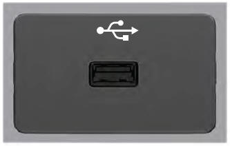
USB Port
WARNING: Driving while distracted can result in loss of vehicle control, crash and injury. We strongly recommend that you use extreme caution when using any device that may take your focus off the road. Your primary responsibility is the safe operation of your vehicle. We recommend against the use of any hand-held device while driving and encourage the use of voice-operated systems when possible. Make sure you are aware of all applicable local laws that may affect the use of electronic devices while driving.
USB A