Lincoln Corsair: Engine - 2.0L EcoBoost (177kW/240PS) – MI4 / General Procedures - Balance Shaft Backlash
Special Tool(s) /
General Equipment
 |
100-002
(TOOL-4201-C)
Holding Fixture with Dial Indicator Gauge |
 |
303-1688
Preload Tool, Balance Shaft |
 |
303-507
Timing Peg, Crankshaft TDC
TKIT-2001N-FLM
TKIT-2001N-ROW |
Check
-
Install the special tool and rotate the crankshaft
slowly clockwise until the crankshaft balance weight is up against the
Crankshaft TDC Timing Peg. The engine is now at TDC .
Use Special Service Tool: 303-507
Timing Peg, Crankshaft TDC.
-
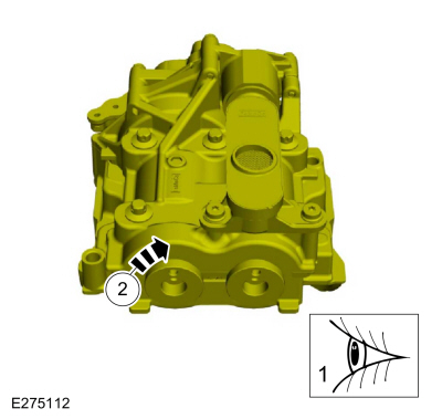
Mark the balancer unit and shafts on the top for reference that the balancer unit is at TDC .
-
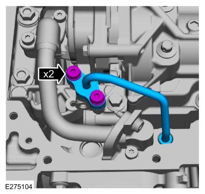
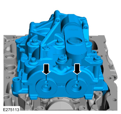
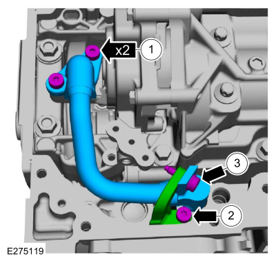
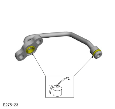
Remove the bolts and the oil outlet tube.
-
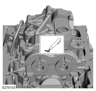
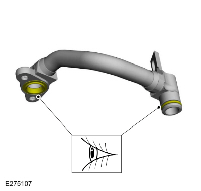
Inspect the oil outlet tube O-ring seals and replace if damaged.
-
-
Remove the oil inlet tube-to-bracket bolt.
-
Remove the bolt and the oil inlet tube bracket.
-
Remove the bolts and the oil inlet tube.
-
Inspect the oil inlet tube O-ring seals and replace if damaged.
-
NOTE:
Due to the precision interior construction of the balancer unit, it should not be disassembled.
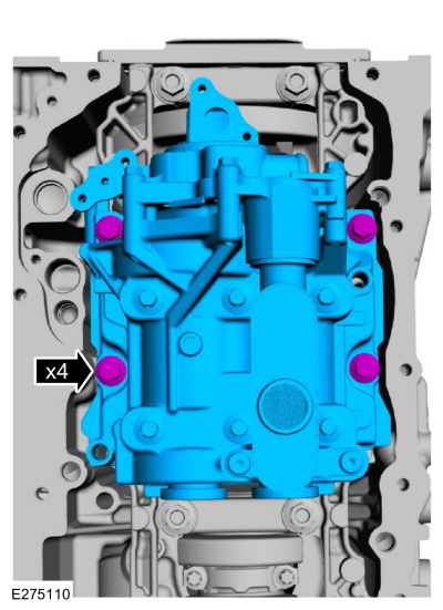
Remove the bolts and the balance unit.
-
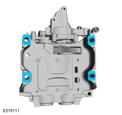
Remove the adjustment shims from the seat faces of the balancer unit.
-
-
Visually inspect the balancer unit gear for damage.
-
Verify that the shaft turns smoothly.
-
If there is any damage or malfunction, replace the balancer unit.
-
Install the master adjustment shims (No. 50) on the seat faces of the balancer unit.
-
With the balancer unit shaft marks at the TDC
position, slowly install the balancer unit to the cylinder block to
avoid interference between the crankshaft drive gear and the balancer
unit driven gear.
-
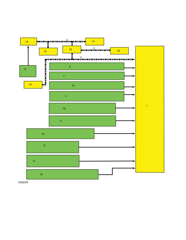
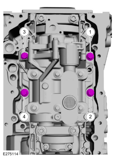
Install the bolts and tighten in sequence shown.
Torque:
Stage 1:
27 lb.ft (36 Nm)
Stage 2:
60°
-
Loosen the bolts.
-
Tighten the bolts in sequence shown.
Torque:
Stage 1:
133 lb.in (15 Nm)
Stage 2:
45°
-
Remove Special Service Tool: 303-507
Timing Peg, Crankshaft TDC.
-
Rotate the crankshaft to confirm that there are no
meshing problems between the balancer unit gear and the crankshaft gear.
-
Install the special tool and rotate the crankshaft
slowly clockwise until the crankshaft balance weight is up against the
Crankshaft TDC Timing Peg. The engine is now at TDC .
Use Special Service Tool: 303-507
Timing Peg, Crankshaft TDC.
-
Remove Special Service Tool: 303-507
Timing Peg, Crankshaft TDC.
 |
|
-
NOTE:
Measure the backlash and verify that it is within
specified range at all of the following 6 positions: 10 degrees, 30
degrees, 100 degrees, 190 degrees, 210 degrees and 280 degrees. It will
be necessary to reset the measuring equipment between measurements.
NOTE:
The measurement must be taken with the Dial
Indicator Gauge with Holding Fixture, a 5-mm Allen wrench and worm clamp
set up as shown.
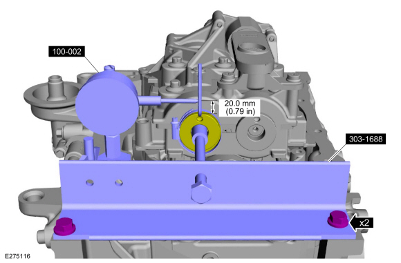
-
Mark the Allen wrench with a file 20 mm (0.79 in) above the driven gear top surface.
-
Install the balance shaft preload tool and bolts as shown.
Use Special Service Tool: 303-1688
Preload Tool, Balance Shaft.
-
Install and position the dial indicator gauge with
holding fixture on the Allen wrench 20 mm (0.79 in) as shown.
Use Special Service Tool: 100-002
(TOOL-4201-C)
Holding Fixture with Dial Indicator Gauge.
-
Rotate the crankshaft clockwise and measure the
backlash at all of the following 6 positions: 10 degrees, 30 degrees,
100 degrees, 190 degrees, 210 degrees and 280 degrees.
 |
|
-
Using the backlash measurement, select the proper shims from the Adjustment Shim Selection Table.
-
Backlash
-
Selection shim (No.)
-
Shim thickness
-
Remove the bolts and the balance unit.
-
Remove the master adjustment shims (No. 50) from the balancer unit.
-
Install the selected adjustment shims on the seat faces of the balancer unit from the chart above.
-
Install the special tool and rotate the crankshaft
slowly clockwise until the crankshaft balance weight is up against the
Crankshaft TDC Timing Peg. The engine is now at TDC .
Use Special Service Tool: 303-507
Timing Peg, Crankshaft TDC.
-
With the balancer unit shaft marks at the TDC
position, slowly install the balancer unit to the cylinder block to
avoid interference between the crankshaft drive gear and the balancer
unit driven gear.
-
Install the bolts and tighten in sequence shown.
Torque:
Stage 1:
133 lb.in (15 Nm)
Stage 2:
45°
-
Remove Special Service Tool: 303-507
Timing Peg, Crankshaft TDC.
|
|
-
NOTE:
Measure the backlash and verify that it is within
specified range at all of the following 6 positions: 10 degrees, 30
degrees, 100 degrees, 190 degrees, 210 degrees and 280 degrees. It will
be necessary to reset the measuring equipment between measurements.
NOTE:
The measurement must be taken with the Dial
Indicator Gauge with Holding Fixture, a 5-mm Allen wrench and worm clamp
set up as shown.
-
Mark the Allen wrench with a file 20 mm (0.79 in) above the driven gear top surface.
-
Install the balance shaft preload tool and bolts as shown.
Use Special Service Tool: 303-1688
Preload Tool, Balance Shaft.
-
Install and position the dial indicator gauge with
holding fixture on the Allen wrench 20 mm (0.79 in) as shown.
Use Special Service Tool: 100-002
(TOOL-4201-C)
Holding Fixture with Dial Indicator Gauge.
-
Rotate the crankshaft clockwise and measure the
backlash at all of the following 6 positions: 10 degrees, 30 degrees,
100 degrees, 190 degrees, 210 degrees and 280 degrees.
-
If the backlash exceeds the specified range of 0.040
to 0.140 mm (0.00157 to 0.0055 in), install a new balancer unit and
repeat the procedure.
|
|
-
Lubricate the oil inlet tube O-ring seals with clean engine oil.
-
-
Install the oil inlet tube and the bolts.
Torque:
97 lb.in (11 Nm)
-
Install the oil inlet tube bracket and the bolt.
Torque:
97 lb.in (11 Nm)
-
Install the oil inlet tube-to-bracket bolt.
Torque:
97 lb.in (11 Nm)
-
Lubricate the oil outlet tube O-ring seals with clean engine oil.
-
Install the oil outlet tube and the bolts.
Torque:
97 lb.in (11 Nm)
For engine mechanical diagnosis and testing, REFER to: Engine (303-00 Engine System - General Information, Diagnosis and Testing). For DTC (Diagnostic Trouble Code) related concerns, REFER to the Master DTC Chart...
Special Tool(s) /
General Equipment
Oil Drain Equipment
Draining
With the vehicle in NEUTRAL, position it on a hoist.
Refer to: Jacking and Lifting - Overview (100-02 Jacking and Lifting, Description and Operation)...
Other information:
Removal
Remove the valve cover.
Refer to: Valve Cover (303-01A Engine - 2.0L EcoBoost (177kW/240PS) – MI4, Removal and Installation).
Remove the high-pressure fuel pump drive unit bolts, then remove the high-pressure fuel pump drive unit...
Diagnostic Trouble Code (DTC) Chart
Diagnostics in this manual assume a certain skill level and knowledge of Ford-specific diagnostic practices. REFER to: Diagnostic Methods (100-00 General Information, Description and Operation).
Module
DTC
Description
Action
PCM
P0420:00
Catalyst System Efficiency Below Threshold (Bank 1): No Sub Type Information
GO to Pinpoint Test HF
PC..


 Diagnosis and Testing - Engine
 General Procedures - Engine Oil Draining and Filling
 Select the settings option on
the
feature bar.
Select the settings option on
the
feature bar.