Lincoln Corsair: Automatic Transmission - 8-Speed Automatic Transmission – 8F35/8F40 / Diagnosis and Testing - Special Testing Procedures
Principles of Operation
Line Pressure Test
This test verifies the line pressure is within specification.
-
Remove the air cleaner.
REFER to: Air Cleaner (303-12B Intake Air Distribution and Filtering - 2.3L EcoBoost (199kW/270PS), Removal and Installation).
-
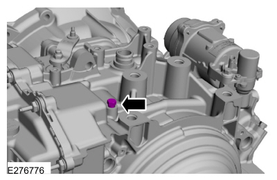
Connect the transmission fluid pressure gauge (307-004) to the line pressure tap.
-
Install the air cleaner.
REFER to: Air Cleaner (303-12B Intake Air Distribution and Filtering - 2.3L EcoBoost (199kW/270PS), Removal and Installation).
-
NOTE: Some transmission calibrations may maximize line pressure (300 PSI (2068 kPa)) during warm-up. Commanding LINEDSD# may have minimal effect.
Start the engine, allow TFT to reach normal operating temperature (if possible) and check the line pressure.
-
Using a diagnostic scan tool, monitor and compare the PID LINEDSD# to
actual measured pressure. Actual measured pressure should be within 10
PSI (69 kPa) of PID
LINEDSD#. Raise engine RPM to 2000 RPM and verify LPC operation by
monitoring LINE pressure while commanding LINEDSD# up and down.
-
If the line pressure is not within specification, see the Line Pressure Diagnosis Chart for possible source.
-
Remove the air cleaner.
REFER to: Air Cleaner (303-12B Intake Air Distribution and Filtering - 2.3L EcoBoost (199kW/270PS), Removal and Installation).
-
When the pressure tests are complete, install the line pressure tap plug.
-
Torque: 12 Nm (106 lb-in).
-
Torque: 12 Nm (106 lb-in).
-
Install the air cleaner.
REFER to: Air Cleaner (303-12B Intake Air Distribution and Filtering - 2.3L EcoBoost (199kW/270PS), Removal and Installation).
Line Pressure Diagnosis Chart
| Test Results | Possible Source |
| HIGH at IDLE |
|
| LOW at IDLE |
|
Stall Speed Test
NOTE: Carry out the Line Pressure Test prior to the Stall Speed Test. If line pressure is low, do not carry out the stall test or additional transmission damage will occur. Do not maintain Wide Open Throttle (WOT) in any gear range for more than 5 seconds.
NOTE: If the engine speed exceeds maximum specified rpm, release the accelerator pedal immediately.
NOTE: Only perform the stall speed test with the engine and transmission at normal operating temperatures.
To prevent damage to transmission and driveline components, the PCM will truncate engine torque output when a stall condition exists. Because of this torque truncation, the stall test cannot be used as a diagnostic test for determining the health of the transmission clutches.
The PCM monitors clutch performance and will set one or more DTC s when an undesired slip is detected.
The torque converter stator one-way clutch should hold at idle and during acceleration. A failed one-way clutch can be identified if all of the following conditions/symptoms exist:
- Transmission fluid is clean and free of excessive contamination
- Normal/expected vehicle performance at cruising speed
- Poor engine idle quality. The engine may even stall
- Very poor acceleration/Lack of power
- Very low stall RPM: <1500 RPM. Perform test procedure below:
-
Apply the parking brake.
-
Connect the scan tool. Navigate to Datalogger: PCM
-
Monitor the PID s: APP (%), RPM, LOAD (%) and GEAR_CMD
-
Start the engine.
-
Place the transmission in reverse.
-
Start datalogger recording.
-
With the brake pedal firmly applied, press the accelerator pedal to
100% for 2-3 seconds until engine RPM stabilizes. Release the
accelerator pedal.
-
Place the transmission in neutral.
-
Press the accelerator pedal to maintain 1500 RPM for 10 seconds to
allow the torque converter to cool. Release the accelerator pedal.
-
Place the transmission in drive.
-
With the brake pedal firmly applied, press the accelerator pedal to
100% for 2-3 seconds until engine RPM stabilizes. Release the
accelerator pedal.
-
Place the transmission in neutral.
-
Press the accelerator pedal to maintain 1500 RPM for 10 seconds to
allow the torque converter to cool. Release the accelerator pedal.
-
Turn the engine off.
-
Review the recording. A properly functioning stator one-way clutch should fall within the following parameters:
-
APP = 100%
-
RPM > 1500
-
LOAD < 100%
-
GEAR_CMD = Reverse or 1st Gear commanded
-
APP = 100%
Air Pressure Test

8F35/8F40 Air Ports
| Item | Description |
| 1 | A clutch |
| 2 | B clutch |
| 3 | C clutch |
| 4 | Hydraulic SOWC apply |
| 5 | Hydraulic SOWC release |
| 6 | E clutch |
| 7 | F clutch |
| 8 | TCC apply |
| 9 | TCC release |
| 10 | Pump out |
| 11 | Secondary pump out |
| 12 | Pump recirculate |
| 13 | Lube |
| 14 | To transmission cooler |
| 15 | Line pressure tap, auto start-stop accumulator |
| 16 | Not used |
-
Using a high volume rubber tipped blow gun, apply air pressure to the suspect clutch port for 2-3 seconds.
-
A dull thud indicates the clutch piston is applied.
-
A hissing noise may indicate a leak in the hydraulic passages.
-
A dull thud indicates the clutch piston is applied.
-
While holding the blow gun nozzle firmly against the port in the transmission case, release the trigger.
-
Wait 1-2 seconds.
-
A hissing noise may indicate a leak in the hydraulic passages.
-
A hissing noise may indicate a leak in the hydraulic passages.
-
Remove the blow gun from the port.
-
A sudden release of air pressure indicates the hydraulic passages are capable of holding pressure.
-
No noise may indicate a leak in the hydraulic passages.
-
A sudden release of air pressure indicates the hydraulic passages are capable of holding pressure.
 Diagnosis and Testing - Diagnosis By Symptom
Symptom Chart: Automatic Transmission
Diagnostics in this manual assume a certain skill level and knowledge of Ford-specific diagnostic practices. REFER to: Diagnostic Methods (100-00 General Information, Description and Operation)...
 Diagnosis and Testing - A Clutch
Principles of Operation
For A clutch operation, REFER to: A Clutch (307-01A Automatic Transmission - 8-Speed Automatic Transmission – 8F35/8F40, Description and Operation)...
Other information:
Lincoln Corsair 2020-2026 Owners Manual: Clearing the Garage Door Opener. Reprogramming the Garage Door Opener. Garage Door Opener Radio Frequencies
Clearing the Garage Door Opener Press and hold the outer two function buttons simultaneously for approximately 10 seconds until the indicator light above the buttons flashes rapidly. When the indicator light flashes, release the buttons. Note: You cannot erase individual buttons...
Lincoln Corsair 2020-2026 Owners Manual: Additional Information Contained on the Tire Sidewall for LT Type Tires
Note: Tire Quality Grades do not apply to this type of tire. LT type tires have some additional information beyond those of P type tires; these differences are described below. LT: Indicates a tire, designated by the Tire and Rim Association, that is intended for service on light trucks...
Categories
- Manuals Home
- 1st Generation Lincoln Corsair Owners Manual
- 1st Generation Lincoln Corsair Service Manual
- Auto Hold (IF EQUIPPED)
- Interior Lamps
- Child Safety Locks
- New on site
- Most important about car
360 Degree Camera Cameras
Locating the Rear View Camera

The rear view camera is on the tailgate.
Locating the Front View Camera