Lincoln Corsair: Electric Powertrain Control / Removal and Installation - Inverter System Controller [SOBDMC]
Special Tool(s) /
General Equipment
 |
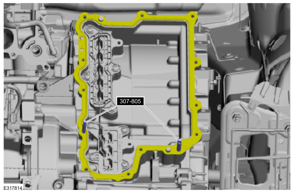
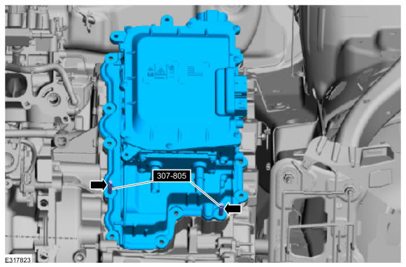
307-805
Alignment Pins (2) |
| Ford Diagnostic Equipment |
Materials
| Name |
Specification |
Engine Oil - SAE 0W-20 - Synthetic Blend Motor Oil
XO-0W20-Q1SP |
WSS-M2C947-B1
|
Removal
NOTICE:
Be sure to keep all fluid and debris away from any open ISC
(inverter system controller) connections, or disassembled/ open
transmission components. Failure to do this will damage the part.
-
NOTE:
This step is only necessary when installing a new component.
Download the module information to the diagnostic tool using the Programmable Modules Installation routine.
Use the General Equipment: Ford Diagnostic Equipment
-
Disable the vehicle high-voltage electrical system.
-
Drain the engine cooling system.
Refer to: Engine Cooling System Draining, Vacuum Filling and Bleeding
(303-03C Engine Cooling - 2.5L Duratec – Hybrid (121kW/164PS) (BG),
General Procedures).
-
Drain the Electric Powertrain Cooling System.
Refer to: Cooling System Filling and Bleeding (303-03D Electric
Powertrain Cooling - 2.5L Duratec – Hybrid (121kW/164PS) (BG), General
Procedures).
-
Remove the air cleaner outlet pipe.
Refer to: Air Cleaner Outlet Pipe (303-12C Intake Air Distribution and
Filtering - 2.5L Duratec – Hybrid (121kW/164PS) (BG), Removal and
Installation).
-
Remove the air cleaner.
Refer to: Air Cleaner (303-12C Intake Air Distribution and Filtering -
2.5L Duratec – Hybrid (121kW/164PS) (BG), Removal and Installation).
-
Remove the intake manifold.
Refer to: Intake Manifold (303-01C Engine - 2.5L Duratec – Hybrid (121kW/164PS) (BG), Removal and Installation).
-
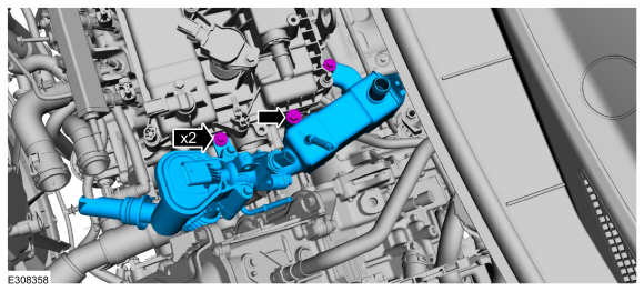
Disconnect the electrical connectors.
-
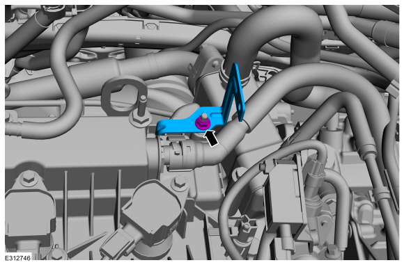
Remove the bolt and position aside the transducer.
-
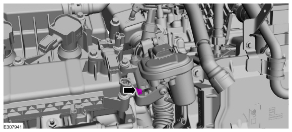
.Remove the nut and fuel hose bracket.
-
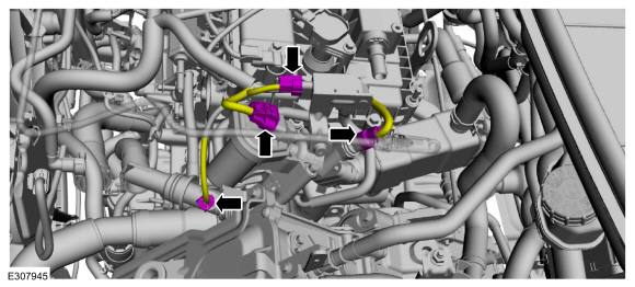
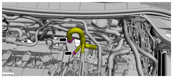
Disconnect the engine coolant hoses.
-
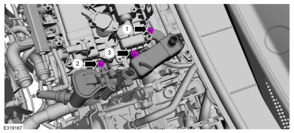
Remove the EGR bracket bolt.
-
-
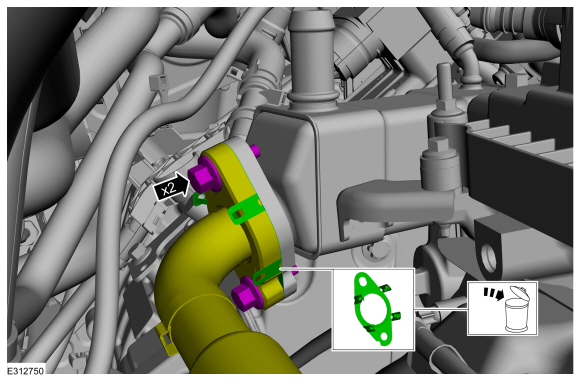
Remove the EGR cooler inlet tube bolts.
-
Remove and discard the EGR cooler inlet tube gasket.
-
Remove the bolts and the EGR valve assembly.
-
Remove and discard the EGR cooler O-ring.
-
NOTICE:
Place absorbent towels under radiator hose to prevent coolant from contacting the ISC.
Disconnect the radiator hose.
-
Remove the bolts and the air cleaner bracket.
-
NOTICE:
Place tape over the connectors on the ISC to prevent contaminating the connector pins.
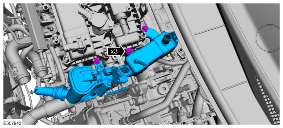
Disconnect the ISC electrical connectors.
-
Remove the bolts and the air cleaner bracket.
-
NOTICE:
Place absorbent towels under the coolant connections to prevent coolant from contacting the ISC.
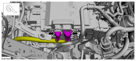
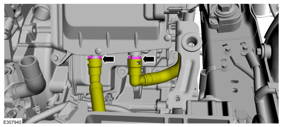
Disconnect the coolant tubes.
-
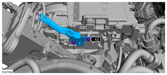
Remove the bolts and position aside the coolant tube.
-
Disconnect the wiring harness retainer.
-
NOTICE:
Place absorbent towels under the coolant connection to prevent coolant from contacting the ISC.
Disconnect the coolant tube.
-
NOTICE:
Place tape over the connectors on the ISC to prevent contaminating the connector pins.
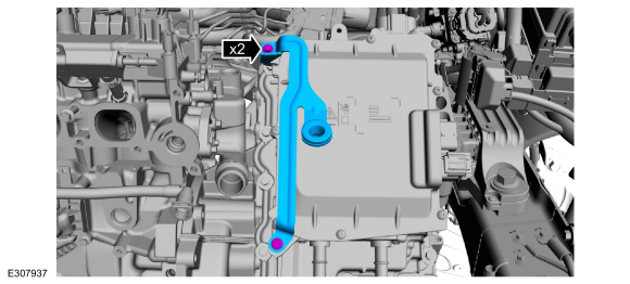
Remove the retainer and disconnect the high-voltage cable from the ISC.
-
NOTICE:
When removing side cover, pull cover straight out
approximately 2 inches before moving upwards or damage to the high
voltage interlock connector may occur.
NOTICE:
Place ISC side cover on a clean surface with high
voltage connector facing upwards or damage to the connector may occur.
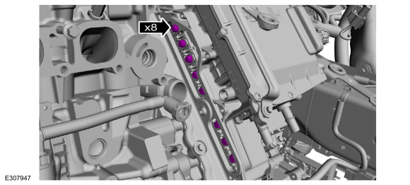
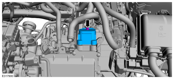
Remove the bolts and remove the ISC side cover.
-
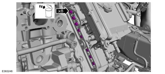
Remove the high voltage terminal bolts. Discard the bolts.
-
NOTICE:
If the ISC is being reinstalled, place the ISC on a
clean surface, transmission side down. It is important to keep all
debris and fluid away from the open ISC or damage to the ISC may occur.
NOTE:
Note the location of the studbolts for assembly.
NOTE:
Cover all coolant ports to avoid spilling coolant
remaining inside the ISC. If the ISC is being replaced, plug the coolant
ports with the caps included with the replacement ISC.
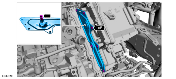
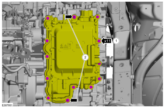
Remove the bolts, studbolts and the ISC.
Installation
-
NOTICE:
Use only a lint free cloth.
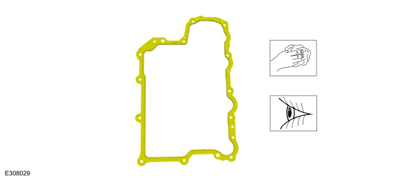
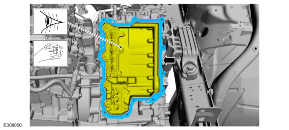
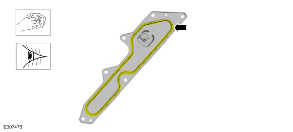
Clean and inspect the ISC gasket, replace if necessary.
-
NOTICE:
Use only a lint free cloth.
Inspect and clean the inside of the transmission cavity of any debris or fluid. Install the ISC gasket.
-
Install the special tools.
Use Special Service Tool: 307-805
Alignment Pins (2).
-
Install the ISC and remove the special tools.
Use Special Service Tool: 307-805
Alignment Pins (2).
-
-
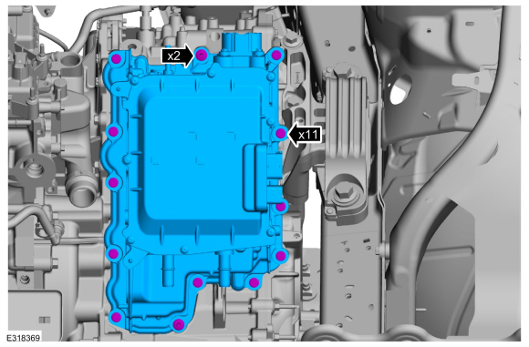
Install the ISC bolts.
Torque:
106 lb.in (12 Nm)
-
Install the ISC studbolts.
Torque:
106 lb.in (12 Nm)
-
Install the high-voltage terminal bolts.
Torque:
106 lb.in (12 Nm)
-
NOTICE:
Use a lint free cloth.
Clean and inspect the ISC side cover and gasket, replace the ISC side cover if necessary.
-
Install the ISC side cover and bolts.
Torque:
93 lb.in (10.5 Nm)
-
Connect the high-voltage cable to the ISC and tighten the retainer.
Torque:
97 lb.in (11 Nm)
-
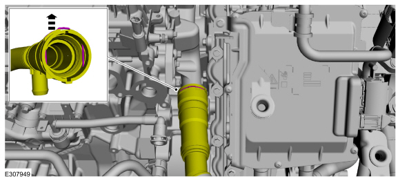
NOTE:
When connecting the coolant tube, push-click-pull on the coolant tube to ensure proper connection.
Connect the coolant tube.
-
Connect the wiring harness retainer.
-
NOTICE:
Be careful not to get residual coolant in the open ISC connectors.
Position back the coolant tube and install the bolts.
Torque:
71 lb.in (8 Nm)
-
NOTE:
When connecting the coolant tubes, push-click-pull on the coolant tubes to ensure proper connection.
Connect the coolant tubes.
-
Install the air cleaner bracket and the bolts.
Torque:
97 lb.in (11 Nm)
-
-
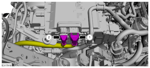
Connect C199A (40 pin connector) and engage the lever lock.
-
Connect C199B (22 pin connector).
-
Install the air cleaner bracket and the bolts.
Torque:
97 lb.in (11 Nm)
-
Connect the radiator hose.
-
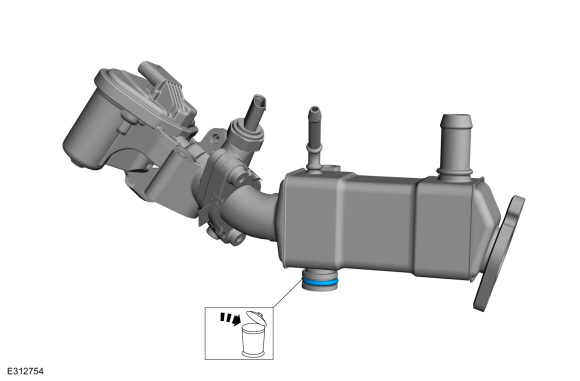
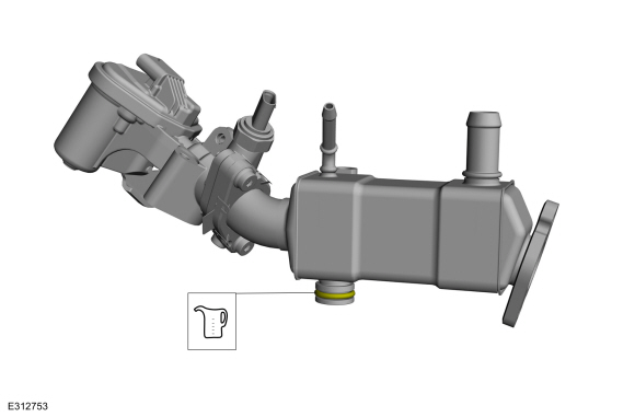
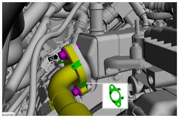
Lubricate the new EGR cooler O-rings with a small amount of engine oil.
Material: Engine Oil - SAE 0W-20 - Synthetic Blend Motor Oil
/ XO-0W20-Q1SP
(WSS-M2C947-B1)
-
Install the EGR valve assembly and hand tighten the bolts.
-
Install the EGR assembly mounting bolt.
Torque:
89 lb.in (10 Nm)
-
Tighten the EGR assembly bolts in the sequence shown.
Torque:
1:
89 lb.in (10 Nm)
2:
89 lb.in (10 Nm)
3:
18 lb.ft (25 Nm)
-
-
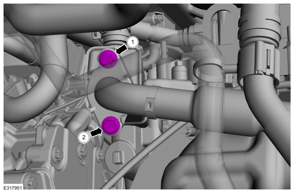
Hand tighten them at this stage.
-
Tighten the bolts in the sequence shown.
Torque:
1:
89 lb.in (10 Nm)
2:
18 lb.ft (24 Nm)
1:
18 lb.ft (24 Nm)
-
Connect the engine coolant hoses.
-
Install the fuel hose bracket and the nut.
Torque:
89 lb.in (10 Nm)
-
Position back the transducer and install the bolt.
Torque:
89 lb.in (10 Nm)
-
Connect the electrical connectors.
-
Install the intake manifold.
Refer to: Intake Manifold (303-01C Engine - 2.5L Duratec – Hybrid (121kW/164PS) (BG), Removal and Installation).
-
Install the air cleaner.
Refer to: Air Cleaner (303-12C Intake Air Distribution and Filtering -
2.5L Duratec – Hybrid (121kW/164PS) (BG), Removal and Installation).
-
Install the air cleaner outlet pipe.
Refer to: Air Cleaner Outlet Pipe (303-12C Intake Air Distribution and
Filtering - 2.5L Duratec – Hybrid (121kW/164PS) (BG), Removal and
Installation).
-
Connect the vehicle high-voltage electrical system.
-
Fill the engine cooling system.
Refer to: Engine Cooling System Draining, Vacuum Filling and Bleeding
(303-03C Engine Cooling - 2.5L Duratec – Hybrid (121kW/164PS) (BG),
General Procedures).
-
Fill and bleed the Electric Powertrain Cooling System.
Refer to: Cooling System Filling and Bleeding (303-03D Electric
Powertrain Cooling - 2.5L Duratec – Hybrid (121kW/164PS) (BG), General
Procedures).
-
NOTE:
This step is only necessary when installing a new component.
Upload the module information from the diagnostic tool
to the module using the Programmable Modules Installation routine.
Use the General Equipment: Ford Diagnostic Equipment
-
NOTE:
This step is only necessary when installing a new component.
If the ISC was replaced, perform the Transmission Strategy Download.
Refer to: Transmission Strategy Download (307-01B Automatic Transmission - Automatic Transmission – HF45, General Procedures).
-
NOTE:
This step is only necessary when installing a new component.
If the ISC was replaced, perform the Module Initialization procedure.
Refer to: Anti-Theft Key Programming - Scan Tool (419-01B Passive Anti-Theft System (PATS), General Procedures).
Removal
NOTE:
Removal steps in this procedure may contain installation details.
Drain the Electric Powertrain Cooling System.
Refer to: Cooling System Filling and Bleeding (303-03D Electric
Powertrain Cooling - 2...
Other information:
Transmission Cooling
This
vehicle is equipped with an external transmission fluid cooler. The
transmission fluid cooler is an oil-to-coolant fluid cooler which is
mounted to the lower LH side of the
transmission. The cooling system also consists of a coolant control
valve mounted to the upper rear of the transmission. The transmission
fluid flows from the transmission to the transmission fl..
Special Tool(s) /
General Equipment
205-153
(T80T-4000-W)
Handle
307-758Installer, Axle Seal -FWD
Flat Headed Screw Driver
Removal
Remove the RH halfshaft.
Refer to: Front Halfshaft RH - AWD (205-04 Front Drive Halfshafts, Removal and Installation).
Remove and discard the RH halfshaft seal.
Use the General Equipment: Flat Headed Screw Driver
..


 Removal and Installation - High Voltage Battery Coolant Temperature Sensor
 Select the settings option on
the
feature bar.
Select the settings option on
the
feature bar.