Lincoln Corsair: Hydraulic Brake Actuation / Removal and Installation - Brake Pedal and Bracket
Removal
NOTE: Removal steps in this procedure may contain installation details.
-
Remove the cowl panel grille
Refer to: Cowl Panel Grille (501-02) .
-
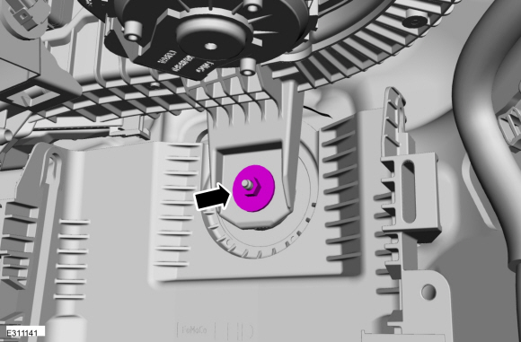
Remove the 2 LH side (under hood) instrument panel bolts
Torque: 35 lb.ft (48 Nm)
 |
-
Position the manual steering column adjuster lever in the down position.
 |
-
Remove the bolts and the lower steering column shroud.
Torque: 17 lb.in (1.9 Nm)
 |
-
Release the clips and remove the LH instrument panel end cap.
 |
-
-
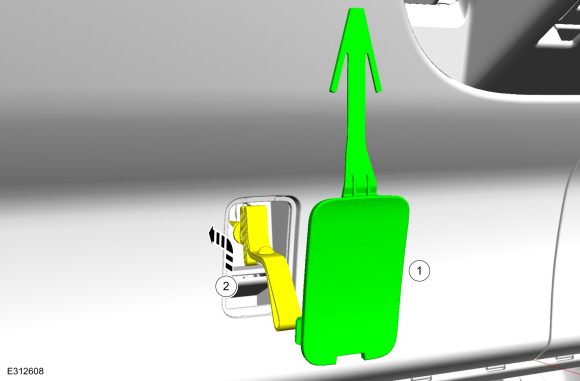
Remove the cover.
-
Lift the cable and strap upward and reward to disengage from the lower trim panel.
-
Remove the cover.
 |
-
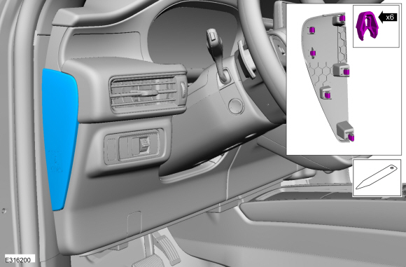
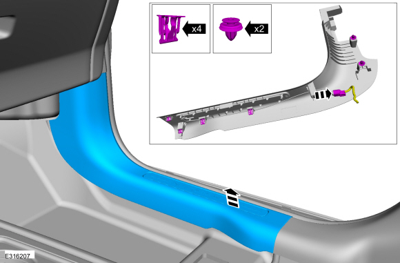
Release the clips and remove the LH trim panel.
-
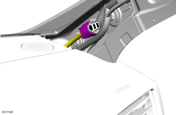
Disconnect the electrical connector.
-
Disconnect the electrical connector.
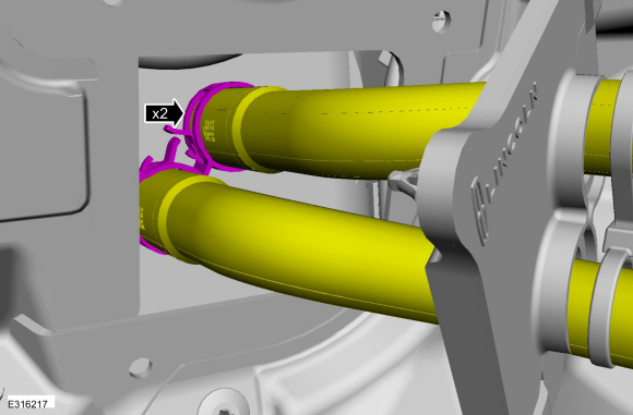 |
-
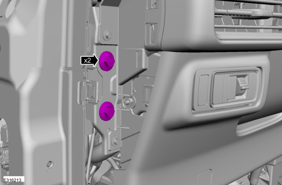
Remove the bolts.
Torque: 35 lb.ft (48 Nm)
 |
-
Remove the accelerator pedal.
Refer to: Accelerator Pedal (310-02) .
-
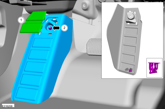
NOTICE: Do not service the brake pedal or brake booster without first removing the stoplamp switch. The switch must be removed with the brake pedal in the at-rest position. The switch plunger must be compressed for the switch to rotate in the bracket. Attempting to remove the switch when the plunger is extended (during pedal apply) will result in damage to the switch.
Remove the stoplamp switch.
Refer to: Stoplamp Switch (417-01) .
-
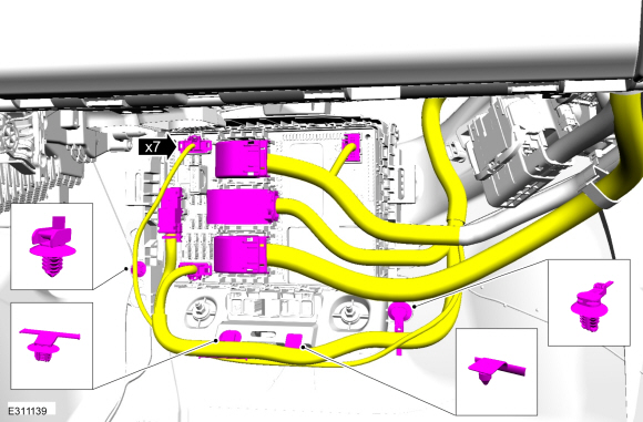
Detach the harness retainers and position the wiring aside.
 |
-
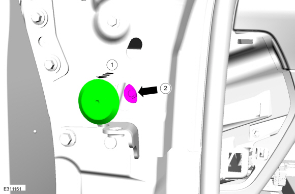
Remove and discard the clevis pin.
 |
-
Remove the 5 brake pedal bracket nuts.
 |
-
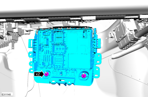
NOTE: Have an assistant to pull the HCU away from the cowl enough to allow the brake pedal bracket to clear the studs.
-
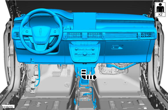
Pull the LH side of the instrument panel away from the cowl slightly.
-
Remove the brake pedal and bracket.
-
Pull the LH side of the instrument panel away from the cowl slightly.
 |
Installation
-
NOTICE: Do not press, pull or otherwise move the brake pedal while installing the stoplamp switch. The switch must be installed with the booster push rod attached to the brake pedal and with the brake pedal in the at-rest position. Installing the switch with the brake pedal in any other position will result in incorrect adjustment and may damage the switch.
To install, reverse the removal procedure.
-
Install the 5 brake pedal bracket nuts in the sequence shown.
Torque: 18 lb.ft (25 Nm)
 |
 Removal and Installation - Brake Fluid Reservoir
Removal
NOTE:
Removal steps in this procedure may contain installation details.
Remove the EBB .
Refer to: Electric Brake Booster (EBB) (206-09 Anti-Lock Brake System (ABS) and Stability Control, Removal and Installation)...

Other information:
Lincoln Corsair 2020-2026 Service Manual: Description and Operation - Input Shaft
Input Shaft Exploded View Item Description 1 B (4, 6, R)/E (5, 6, 7, 8) clutch hub 2 Input shaft 3 B (4, 6, R) clutch 4 E (5, 6, 7, 8) clutch 5 Input sun gear 6 Torque converter Input Shaft Cutaway View Input Shaft The input shaft is part of the ..
Lincoln Corsair 2020-2026 Service Manual: General Procedures - Exhaust Manifold Cleaning and Inspection
Special Tool(s) / General Equipment Feeler Gauge Cleaning Clean the exhaust manifold using a suitable solvent. Use a plastic scraping tool to clean the gasket sealing surfaces. Inspection NOTE: New exhaust manifold gaskets, studs, nuts and/or bolts must be installed when an exhaust manifold is serviced. NOTE: Use a Straightedge that is calibrated by the ..
Categories
- Manuals Home
- 1st Generation Lincoln Corsair Owners Manual
- 1st Generation Lincoln Corsair Service Manual
- Capacities and Specifications - 2.0L
- Interior Lamps
- Overhaul - Main Control Valve Body
- New on site
- Most important about car
Keyless Starting
Note: The keyless starting system may not function if the key is close to metal objects or electronic devices such as cellular phones.
Note: A valid key must be located inside your vehicle to switch the ignition on and start the engine.
Ignition Modes