Lincoln Corsair: Automatic Transmission - 8-Speed Automatic Transmission – 8F35/8F40 / Description and Operation - Transmission Description - System Operation and Component Description
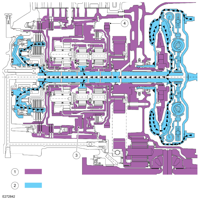
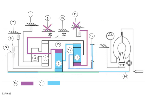
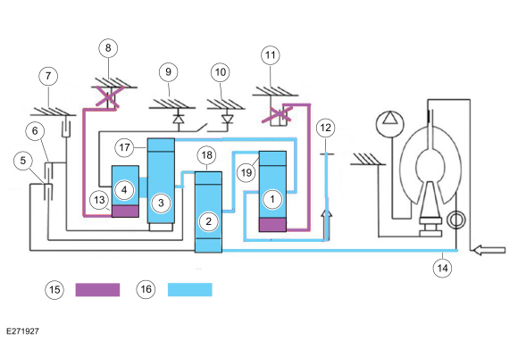
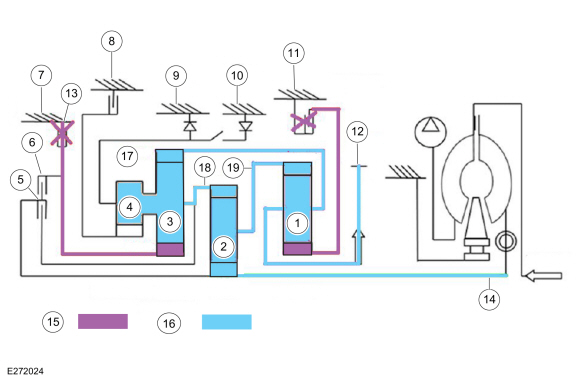
System Diagram
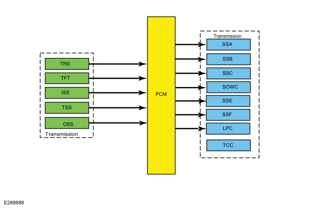
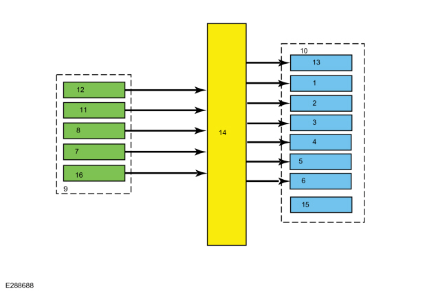
| Item | Description |
|---|---|
| 1 | SSB |
| 2 | SSC |
| 3 | SOWC |
| 4 | SSE |
| 5 | SSF |
| 6 | LPC |
| 7 | TSS |
| 8 | ISS |
| 9 | Transmission |
| 10 | Transmission |
| 11 | TFT |
| 12 | TRS |
| 13 | SSA |
| 14 | PCM |
| 15 | TCC |
| 16 | OSS |
Network Message Chart
| Broadcast Message | Originating Module | Message Purpose |
|---|---|---|
| Engine speed | PCM | Directly affects shift scheduling, TCC control, line pressure and transmission diagnostics. Indirectly affects shift pressure control. |
| Engine torque estimate | PCM | Directly affects shift pressure control, TCC control and transmission diagnostics. Indirectly affects shift scheduling and TCC scheduling. |
| APP | PCM | Directly affects shift scheduling, TCC scheduling and transmission diagnostics. Indirectly affects TCC control and shift control. |
| Commanded engine torque | PCM | Directly affects shift scheduling, TCC scheduling and transmission diagnostics. Indirectly affects shift control. |
| BPP | PCM | Directly affects shift scheduling and TCC scheduling. |
System Operation
The PCM and its input/output network controls shift timing and line pressure (shift feel).
The transmission control strategy is separate from the engine control strategy in the PCM , although some of the input signals are shared. When determining the best operating strategy for transmission operation, the PCM uses input information from engine and driver related sensors and switches.
In addition, the PCM receives input signals from transmission related sensors and switches and uses these signals to determine transmission operating strategy.
Using all of these input signals, the PCM can determine when the time and conditions are right for a shift or when to apply or release the TCC . It also determines the best line pressure to optimize shift engagement feel. To accomplish this, the PCM uses output solenoids to control transmission operation.
Component Description
Sensors and Switches
The PCM controls the transmission electronic functions through input signals received from the engine and transmission sensors. The PCM uses these inputs to control line pressure, shift time, TCC and shift solenoids.
| Item | Description |
| TFT sensor | This sensor is located in the main control. It is a temperature-sensitive device called a thermistor. The resistance value of the TFT sensor varies with temperature change. The PCM monitors the voltage across the TFT sensor to determine the temperature of the transmission fluid. The PCM uses this initial signal to determine whether a cold start shift schedule is necessary. The cold start shift schedule allows delayed shifts when the transmission fluid is cold to help warm the transmission fluid. The PCM also inhibits TCC operation at low transmission fluid temperatures and adjusts line pressure for temperature. |
| TR sensor | The park by wire dual range TR sensor indicates the state of the park system. The cable shift dual range TR sensor determines the customer selected shifter position. |
| TSS/ISSA (Turbine Shaft Speed/Intermediate Shaft Speed Assembly) sensor | The TSS/ISSA (Turbine Shaft Speed/Intermediate Shaft Speed Assembly) sensor is a Hall-effect type sensor that provides a turbine shaft or intermediate shaft speed signal to the PCM . The TSS (Turbine Shaft Speed) signal changes in frequency as the rotating speed of the trigger wheel, part of the B clutch cylinder, varies. The ISSA (Intermediate Shaft Speed Assembly) reads off of the reaction sun gear and is part of the TSS (Turbine Shaft Speed) sensor. The TSS/ISSA (Turbine Shaft Speed/Intermediate Shaft Speed Assembly) information is compared to engine rpm to determine TSS/ISSA (Turbine Shaft Speed/Intermediate Shaft Speed Assembly) performance. TSS/ISSA (Turbine Shaft Speed/Intermediate Shaft Speed Assembly) is also compared to the OSS to determine shift quality and clutch performance. |
| OSS sensor | The OSS sensor is a Hall-effect type sensor that provides an OSS signal to the PCM . The OSS signal changes in frequency as the rotating speed of the trigger wheel, part of the park gear, varies. The OSS is used for shift scheduling. The OSS is also compared to the TSS/ISSA (Turbine Shaft Speed/Intermediate Shaft Speed Assembly) to determine shift quality and clutch performance. |
| Transmission Fluid Pressure (TFP) sensor | Transmission Fluid Pressure (TFP) sensors for clutch A (TFP A) and B (TFP B) have been added to improve diagnostic capability for non-electrical (stuck solenoid or valve) faults. Pressure readings are used to monitor the status of specified clutch systems during operation. |
Typical TR Sensors PWM Output
| Mechanical Shifter | Transmission Range Sensor A | Transmission Range Sensor B | ||
| Gear | Min | Max | Min | Max |
| P | 7 | 17 | 93 | 82 |
| R | 31 | 47 | 69 | 52 |
| N | 51 | 64 | 49 | 36 |
| D | 67 | 80 | 33 | 20 |
| Sport/Man | 82 | 94 | 17 | 7 |
| Shift By Wire | Transmission Range Sensor A | Transmission Range Sensor B | ||
| Gear | Min | Max | Min | Max |
| P | 8 | 20 | 92 | 79 |
| Out of Park | 65 | 75 | 34 | 24 |
| Mechanical Override | 75 | 92 | 24 | 8 |
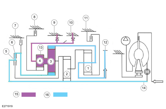
System Diagram
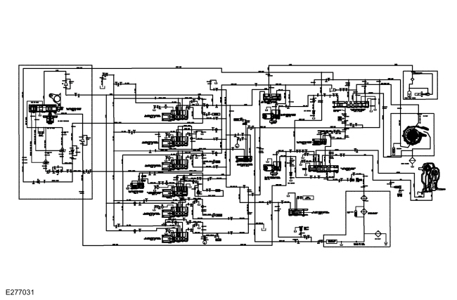
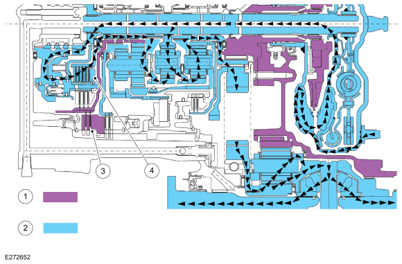
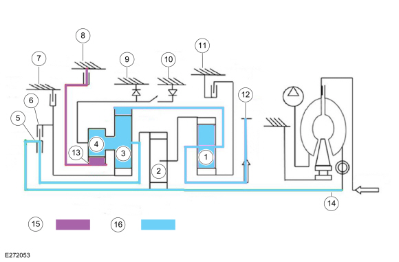
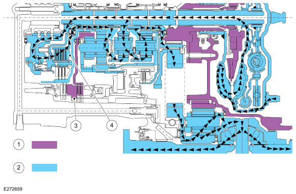
8F35 Hydraulic Schematic View
Solenoid Body
Solenoids
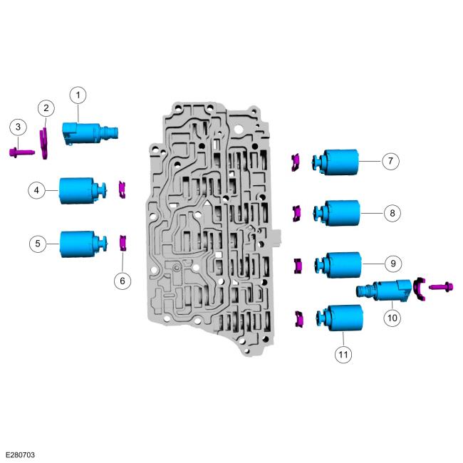
| Item | Description |
| 1 | TCC solenoid (7G136) |
| 2 | Retainer (7H186) |
| 3 | Bolt (W712658) |
| 4 | SSE solenoid (7J136) |
| 5 | SSC solenoid (7J136) |
| 6 | Clutch solenoid retainer (7G007) |
| 7 | SSA solenoid (7J136) |
| 8 | SSF solenoid (7J136) |
| 9 | SSB solenoid (7J136) |
| 10 | LPC solenoid (7G383) |
| 11 | SSD solenoid (7J136) |
Solenoid Body
This transmission uses 2 types of solenoids: CIDAS and variable force solenoids.
The solenoid body contains 8 solenoids: 6 shift solenoids SSA , SSB , SSC , SSD , SSE and SSF , 1 TCC solenoid and 1 LPC solenoid. The TCC solenoid is identified by the green electrical connector. The LPC solenoid is identified by the blue electrical connector. The TFT sensor is located in the main control.
The solenoid body has a unique strategy data file that must be downloaded to the PCM . There is a 12-digit solenoid body identification and a 13-digit solenoid body strategy for each solenoid body. When a new solenoid body or transmission is installed, the scan tool must be used to get the solenoid body strategy data file and download it into the PCM .
If the PCM is replaced and the PCM data cannot be inhaled or exhaled, the solenoid body identification and solenoid body strategy must be downloaded into the PCM .
Shift Solenoids
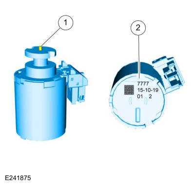
| Item | Description |
| 1 | Armature/pin assembly |
| 2 | Part information |
This transmission utilizes six shift solenoids (A-F) that are normally low CIDAS . Unlike previous shift solenoids they are mechanical in nature in that no transmission fluid passes through them. CIDAS s use an armature/pin assembly that moves a control valve in the main control valve body to control and apply hydraulic fluid pressure. Each clutch (A-F) has a corresponding shift solenoid (A-F) that is directly proportional in that zero current equals zero pressure and maximum current equals maximum pressure. Since there is no pressure with zero current if the power is interrupted to the shift solenoids none of the clutch packs are able to engage.
Torque Converter Clutch (TCC) Line Pressure Control (LPC)
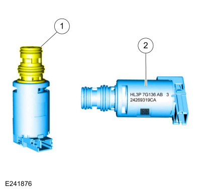
| Item | Description |
| 1 | Solenoid nozzle |
| 2 | Part information |
The TCC solenoid is a normally low variable force solenoid. The TCC solenoid uses proportional operation. As the current from the TCM decreases, the pressure from the solenoid decreases. As the current from the TCM increases, the pressure from the solenoid increases. The LPC solenoid is a normally high variable force solenoid. When current is high, no fluid pressure passes through the solenoid into the control circuits. When current applied to the solenoid is low, full pressure is passed through to the LPC control circuit and the main regulator valve.
Secondary Fluid Filter
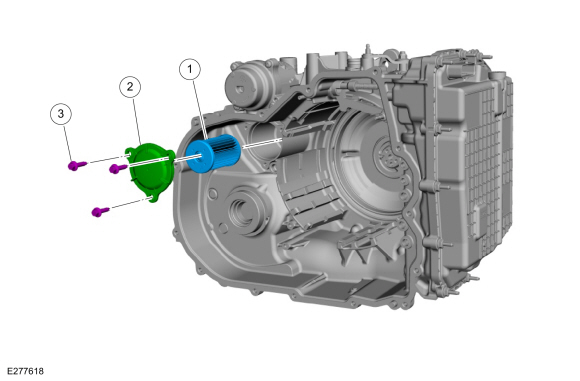
| Item | Description |
| 1 | Secondary fluid filter |
| 2 | Cover |
| 3 | Bolts (3 required) |
This transmission is equipped with a secondary fluid filter. This 30-micron filter is located at the cooler return passage in the case and filters out any debris that would have otherwise entered the transmission from the cooling system or during service when the lines are disconnected. The fluid passing through this filter goes directly into the lube circuits and then drains back down to the sump. The filter includes a bypass valve that allows fluid to continue to supply the lube circuit in the event the filter becomes blocked or restricted.
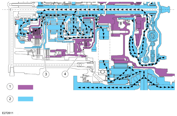
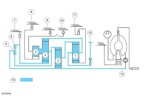
Park
Park Clutch Application Chart
| Gear | A Clutch (1,2,3,4,5) | B Clutch (4,6,R) | C Clutch (3,7) | One-Way Clutch (1) Hydraulic Selectable One-Way clutch | E Clutch (5,6,7,8) | F Clutch (2,8) | |
| Park | H | H | |||||
| Planetary components | Output sun | Reaction sun | Overdrive sun | Overdrive/reaction input ring gear | Input ring gear | Overdrive sun | |
H = Holding
Park Position Solenoid Operation Chart
| Base Selector Lever Position | PCM Commanded Gear | SSA (1,2,3,4,5) | SSB (4,6,R) | SSC (3,7) | One-Way Clutch (1) | SSD (R,1) | SSE (5,6,7,8) | SSF (2,8) |
| P | P | Off | Off | Off | On | Off | On |
Powerflow
| Item | Description |
| 1 | Output planetary |
| 2 | Input planetary |
| 3 | Reaction planetary |
| 4 | Overdrive planetary |
| 5 | E (5, 6, 7, 8) clutch |
| 6 | B (4, 6, R) clutch |
| 7 | C (3, 7) clutch |
| 8 | F (2, 8) clutch |
| 9 | One-Way Clutch (OWC) |
| 10 | Hydraulic SOWC |
| 11 | A (1, 2, 3, 4, 5) clutch |
| 12 | 0 rpm |
| 13 | 0 rpm |
| 14 | 1000 rpm |
| 15 | Held components |
| 16 | Driven components |
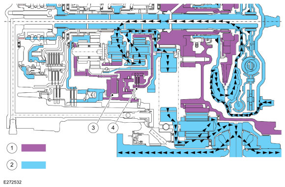
Park Position
| Item | Description |
| 1 | Held components |
| 2 | Driven components |
| 3 | Hydraulic SOWC |
| 4 | Park pawl |
- With the vehicle in PARK, the hydraulic SOWC holds the overdrive/reaction carrier stationary in anticipation of Reverse or 1st gear engagement.
- All gear element speeds can be predicted and a consistent engagement feel can be achieved.
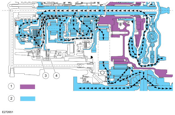
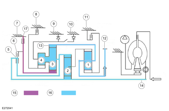
Reverse
Reverse Clutch Application Chart
| Gear | A Clutch (1,2,3,4,5) | B Clutch (4,6,R) | C Clutch (3,7) | One-Way Clutch (1) Hydraulic Selectable One-Way Clutch (SOWC) | E Clutch (5,6,7,8) | F Clutch (2,8) | |
| Reverse | D | H | |||||
| Planetary components | Output sun | Reaction sun | Overdrive sun | Overdrive/reaction input ring gear | Input ring gear | Overdrive sun | |
H = Holding
D = Driving
Reverse Position Solenoid Operation Chart
| Base Selector Lever Position | PCM Commanded Gear | SSA (1,2,3,4,5) | SSB (4,6,R) | SSC (3,7) | One-Way Clutch (1) | SSD (R,1) | SSE (5,6,7,8) | SSF (2,8) |
| R | R | Off | On | Off | On | Off | Off |
Powerflow
| Item | Description |
| 1 | Output planetary |
| 2 | Input planetary |
| 3 | Reaction planetary |
| 4 | Overdrive planetary |
| 5 | E (5, 6, 7, 8) clutch |
| 6 | B (4, 6, R) clutch |
| 7 | C (3, 7) clutch |
| 8 | F (2, 8) clutch |
| 9 | One-Way Clutch (OWC) |
| 10 | Hydraulic SOWC |
| 11 | A (1, 2, 3, 4, 5) clutch |
| 12 | -337 rpm |
| 13 | 0 rpm |
| 14 | 1000 rpm |
| 15 | Held components |
| 16 | Driven components |
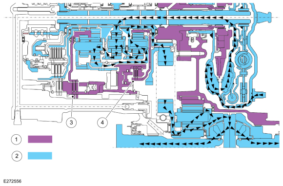
Reverse Position
| Item | Description |
| 1 | Held components |
| 2 | Driven components |
| 3 | B (4, 6, R) clutch |
| 4 | Hydraulic SOWC |
- With the selector lever in REVERSE, the hydraulic SOWC holds the overdrive/reaction carrier stationary.
- The B (4, 6, R) clutch drives the reaction sun gear at turbine shaft speed (1000 rpm).
- The reaction ring and output carrier rotates at -337 rpm or a 2.96:1 reserve ratio.
Neutral
Neutral Clutch Application Chart
| Gear | A Clutch (1,2,3,4,5) | B Clutch (4,6,R) | C Clutch (3,7) | One-Way Clutch (1) Hydraulic Selectable One-Way Clutch (SOWC) | E Clutch (5,6,7,8) | F Clutch (2,8) | |
| Neutral | H | ||||||
| Planetary components | Output sun | Reaction sun | Overdrive sun | Overdrive/reaction input ring gear | Input ring gear | Overdrive sun | |
H = Holding
Neutral Position Solenoid Operation Chart
| Base Selector Lever Position | PCM Commanded Gear | SSA (1,2,3,4,5) | SSB (4,6,R) | SSC (3,7) | One-Way Clutch (1) | SSD (R,1) | SSE (5,6,7,8) | SSF (2,8) |
| N | N | Off | Off | Off | On | Off | Off |
Powerflow
| Item | Description |
| 1 | Output planetary |
| 2 | Input planetary |
| 3 | Reaction planetary |
| 4 | Overdrive planetary |
| 5 | E (5, 6, 7, 8) clutch |
| 6 | B (4, 6, R) clutch |
| 7 | C (3, 7) clutch |
| 8 | F (2, 8) clutch |
| 9 | One-Way clutch (OWC) |
| 10 | Hydraulic SOWC |
| 11 | A (1, 2, 3, 4, 5) clutch |
| 12 | 0 rpm |
| 13 | 0 rpm |
| 14 | 1000 rpm |
| 15 | Held components |
| 16 | Driven components |
Neutral Position
| Item | Description |
| 1 | Held components |
| 2 | Driven components |
| 3 | Hydraulic SOWC |
- With the selector lever in NEUTRAL, the hydraulic SOWC holds the overdrive/reaction planetary carrier stationary.
- The turbine shaft drives the center sun gear.
1st Gear
1st Gear Clutch Application Chart
| Gear | A Clutch (1,2,3,4,5) | B Clutch (4,6,R) | C Clutch (3,7) | One-Way Clutch (1) Hydraulic Selectable One-Way Clutch (SOWC) | E Clutch (5,6,7,8) | F Clutch (2,8) | |
| 1st Gear D | H | H | |||||
| Planetary components | Output sun | Reaction sun | Overdrive sun | Overdrive/reaction input ring gear | Input Ring gear | Overdrive sun | |
H = Holding
1st Gear Solenoid Operation Chart
| Base Selector Lever Position | PCM Commanded Gear | SSA (1,2,3,4,5) | SSB (4,6,R) | SSC (3,7) | One-Way Clutch (1) | SSD (R,1) | SSE (5,6,7,8) | SSF (2,8) |
| D | 1 | On | Off | Off | H | Off | Off | Off |
Powerflow
| Item | Description |
| 1 | Output planetary |
| 2 | Input planetary |
| 3 | Reaction planetary |
| 4 | Overdrive planetary |
| 5 | E (5, 6, 7, 8) clutch |
| 6 | B (4, 6, R) clutch |
| 7 | C (3, 7) clutch |
| 8 | F (2, 8) clutch |
| 9 | One-Way Clutch (OWC) |
| 10 | Hydraulic SOWC |
| 11 | A (1, 2, 3, 4, 5) clutch |
| 12 | 213 rpm |
| 13 | 0 rpm |
| 14 | 1000 rpm |
| 15 | Held components |
| 16 | Driven components |
| 17 | 308 rpm |
1st Gear Position
| Item | Description |
| 1 | Held components |
| 2 | Driven components |
| 3 | One-Way Clutch (OWC) |
| 4 | A (1, 2, 3, 4, 5) clutch |
- In first gear, the A (1, 2, 3, 4, 5) clutch holds the output sun gear stationary.
- The one-way clutch holds the input ring gear stationary.
- The turbine shaft and the input sun gear rotate at 1000 rpm.
- The input carrier and the output ring rotate at 308 rpm.
- The output carrier rotates at 213 rpm or a 4.689:1 ratio.
2nd Gear
2nd Gear Clutch Application Chart
| Gear | A Clutch (1,2,3,4,5) | B Clutch (4,6,R) | C Clutch (3,7) | One-Way Clutch (1) Hydraulic Selectable One-Way Clutch (SOWC) | E Clutch (5,6,7,8) | F Clutch (2,8) | |
| 2nd Gear D | H | H | |||||
| Planetary components | Output sun | Reaction sun | Overdrive sun | Overdrive/reaction input ring gear | Input ring gear | Overdrive sun | |
H = Holding
O/R = Over Running
2nd Gear Solenoid Operation Chart
| Base Selector Lever Position | PCM Commanded Gear | SSA (1,2,3,4,5) | SSB (4,6,R) | SSC (3,7) | One-Way Clutch (1) | SSD (R,1) | SSE (5,6,7,8) | SSF (2,8) |
| D | 2 | On | Off | Off | O/R | Off | Off | On |
Powerflow
| Item | Description |
| 1 | Output planetary |
| 2 | Input planetary |
| 3 | Reaction planetary |
| 4 | Overdrive planetary |
| 5 | E (5, 6, 7, 8) clutch |
| 6 | B (4, 6, R) clutch |
| 7 | C (3, 7) clutch |
| 8 | F (2, 8) clutch |
| 9 | One-Way Clutch (OWC) |
| 10 | Hydraulic SOWC |
| 11 | A (1, 2, 3, 4, 5) clutch |
| 12 | 302 rpm |
| 13 | 0 rpm |
| 14 | 1000 rpm |
| 15 | Held components |
| 16 | Driven components |
| 17 | 302 rpm |
| 18 | 186 rpm |
| 19 | 437 rpm |
2nd Gear Position
| Item | Description |
| 1 | Held components |
| 2 | Driven components |
| 3 | F (2, 8) clutch |
| 4 | A (1, 2, 3, 4, 5) clutch |
- In second gear, the A (1, 2, 3, 4, 5) clutch holds the output sun gear stationary.
- The F (2, 8) clutch holds the overdrive sun gear stationary.
- The turbine shaft and input sun rotate at 1000 rpm.
- The input ring rotates at 186 rpm.
- The input carrier and the output ring rotate at 437 rpm.
- The output carrier rotates at 302 rpm or a 3.306:1 ratio.
3rd Gear
3rd Gear Clutch Application Chart
| Gear | A Clutch (1,2,3,4,5) | B Clutch (4,6,R) | C Clutch (3,7) | One-Way Clutch (1) Hydraulic Selectable One-Way Clutch (SOWC) | E Clutch (5,6,7,8) | F Clutch (2,8) | |
| 3rd Gear D | H | H | |||||
| Planetary components | Output sun | Reaction sun | Overdrive sun | Overdrive/reaction input ring gear | Input ring gear | Overdrive sun | |
H = Holding
O/R = Over Running
3rd Gear Solenoid Operation Chart
| Base Selector Lever Position | PCM Commanded Gear | SSA (1,2,3,4,5) | SSB (4,6,R) | SSC (3,7) | One-Way Clutch (1) | SSD (R,1) | SSE (5,6,7,8) | SSF (2,8) |
| D | 3 | On | Off | On | O/R | Off | Off | Off |
Powerflow
| Item | Description |
| 1 | Output planetary |
| 2 | Input planetary |
| 3 | Reaction planetary |
| 4 | Overdrive planetary |
| 5 | E (5, 6, 7, 8) clutch |
| 6 | B (4, 6, R) clutch |
| 7 | C (3, 7) clutch |
| 8 | F (2, 8) clutch |
| 9 | One-Way Clutch (OWC) |
| 10 | Hydraulic SOWC |
| 11 | A (1, 2, 3, 4, 5) clutch |
| 12 | 332 rpm |
| 13 | 0 rpm |
| 14 | 1000 rpm |
| 15 | Held components |
| 16 | Driven components |
| 17 | 332 rpm |
| 18 | 458 rpm |
| 19 | 480 rpm |
3rd Gear Position
| Item | Description |
| 1 | Held components |
| 2 | Driven components |
| 3 | C (3, 7) clutch |
| 4 | A (1, 2, 3, 4, 5) clutch |
- In third gear, the A (1, 2, 3, 4, 5) clutch holds the output sun gear stationary.
- The C (3, 7) clutch holds the reaction sun gear stationary.
- The turbine shaft and the input sun rotate at 1000 rpm.
- The input ring rotates at 458 rpm.
- The input carrier and the output ring rotate at 480 rpm.
- The output carrier rotates at 332 rpm or a 3.012:1 ratio.
4th Gear
4th Gear Clutch Application Chart
| Gear | A Clutch (1,2,3,4,5) | B Clutch (4,6,R) | C Clutch (3,7) | One-Way Clutch (1)Hydraulic Selectable One-Way Clutch (SOWC) | E Clutch (5,6,7,8) | F Clutch (2,8) | |
| 4th Gear D | H | H | |||||
| Planetary components | Output sun | Reaction sun | Overdrive sun | Overdrive/reaction input ring gear | Input ring gear | Overdrive sun | |
H = Holding
O/R = Over Running
4th Gear Solenoid Operation Chart
| Base Selector Lever Position | PCM Commanded Gear | SSA (1,2,3,4,5) | SSB (4,6,R) | SSC (3,7) | One-Way Clutch (1) | SSD (R,1) | SSE (5,6,7,8) | SSF (2,8) |
| D | 4 | On | On | Off | O/R | Off | Off | Off |
Powerflow
| Item | Description |
| 1 | Output planetary |
| 2 | Input planetary |
| 3 | Reaction planetary |
| 4 | Overdrive planetary |
| 5 | E (5, 6, 7, 8) clutch |
| 6 | B (4, 6, R) clutch |
| 7 | C (3, 7) clutch |
| 8 | F (2, 8) clutch |
| 9 | One-Way Clutch (OWC) |
| 10 | Hydraulic SOWC |
| 11 | A (1, 2, 3, 4, 5) clutch |
| 12 | 520 rpm |
| 13 | 525 rpm |
| 14 | 1000 rpm |
| 15 | Held components |
| 16 | Driven components |
| 17 | 520 rpm |
| 18 | 751 rpm |
4th Gear Position

| Item | Description |
| 1 | Held components |
| 2 | Driven components |
| 3 | B (4, 6, R) clutch |
| 4 | A (1, 2, 3, 4, 5) clutch |
- In fourth gear, the A (1, 2, 3, 4, 5) clutch holds the output sun gear stationary.
- The B (4, 6, R) clutch holds the reaction sun gear at turbine shaft speed (1000 rpm).
- The turbine shaft and input sun rotate at 1000 rpm.
- The input ring rotates at 525 rpm.
- The input carrier and output ring rotate at 751 rpm.
- The output carrier rotates at 520 rpm or a 1.923:1 ratio.
5th Gear
5th Gear Clutch Application Chart
| Gear | A Clutch (1,2,3,4,5) | B Clutch (4,6,R) | C Clutch (3,7) | One-Way Clutch (1) Hydraulic Selectable One-Way Clutch (SOWC) | E Clutch (5,6,7,8) | F Clutch (2,8) | |
| 5th Gear D | H | H | |||||
| Planetary components | Output sun | Reaction sun | Overdrive sun | Overdrive/reaction input ring gear | Input ring gear | Overdrive sun | |
H = Holding
O/R = Over Running
5th Gear Solenoid Operation Chart
| Base Selector Lever Position | PCM Commanded Gear | SSA (1,2,3,4,5) | SSB (4,6,R) | SSC (3,7) | One-Way Clutch (1) | SSD (R,1) | SSE (5,6,7,8) | F Clutch (2,8) |
| D | 5 | On | Off | Off | O/R | Off | On | Off |
Powerflow
| Item | Description |
| 1 | Output planetary |
| 2 | Input planetary |
| 3 | Reaction planetary |
| 4 | Overdrive planetary |
| 5 | E (5, 6, 7, 8) clutch |
| 6 | B (4, 6, R) clutch |
| 7 | C (3, 7) clutch |
| 8 | F (2, 8) clutch |
| 9 | One-Way Clutch (OWC) |
| 10 | Hydraulic SOWC |
| 11 | A (1, 2, 3, 4, 5) clutch |
| 12 | 692 rpm |
| 13 | 0 rpm |
| 14 | 1000 rpm |
| 15 | Held components |
| 16 | Driven components |
5th Gear Position
| Item | Description |
| 1 | Held components |
| 2 | Driven components |
| 3 | E (5, 6, 7, 8) clutch |
| 4 | A (1, 2, 3, 4, 5) clutch |
- In fifth gear, the A (1, 2, 3, 4, 5) clutch holds the output sun gear stationary.
- The E clutch holds the input ring gear at turbine shaft speed (1000 rpm).
- The turbine shaft and the input sun rotate at 1000 rpm.
- The input carrier and the output ring rotate at 1000 rpm.
- The output carrier rotates at 692 rpm or a 1.446:1 ratio.
6th Gear
6th Gear Clutch Application Chart
| Gear | A Clutch (1,2,3,4,5) | B Clutch (4,6,R) | C Clutch (3,7) | One-Way Clutch (1) Hydraulic Selectable One-Way Clutch (SOWC) | E Clutch (5,6,7,8) | F Clutch (2,8) | |
| 6th Gear D | D | D | |||||
| Planetary components | Output sun | Reaction sun | Overdrive sun | Overdrive/reaction input ring gear | Input ring gear/reaction sun | Overdrive sun | |
D = Driving
O/R = Over Running
6th Gear Solenoid Operation Chart
| Base Selector Lever Position | PCM Commanded Gear | SSA (1,2,3,4,5) | SSB (4,6,R) | SSC (3,7) | One-Way Clutch (1) | SSD (R,1) | SSE (5,6,7,8) | F Clutch (2,8) |
| D | 6 | Off | On | Off | O/R | Off | On | Off |
Powerflow
| Item | Description |
| 1 | Output planetary |
| 2 | Input planetary |
| 3 | Reaction planetary |
| 4 | Overdrive planetary |
| 5 | E (5, 6, 7, 8) clutch |
| 6 | B (4, 6, R) clutch |
| 7 | C (3, 7) clutch |
| 8 | F (2, 8) clutch |
| 9 | One-Way Clutch (OWC) |
| 10 | Hydraulic SOWC |
| 11 | A (1, 2, 3, 4, 5) clutch |
| 12 | 1000 rpm |
| 13 | 1000 rpm |
| 14 | Driven components |
6th Gear Position
| Item | Description |
| 1 | Held components |
| 2 | Driven components |
| 3 | B (4, 6, R) clutch |
| 4 | E (5, 6, 7, 8) clutch |
- In sixth gear, the B (4, 6, R) clutch drives the reaction sun gear at turbine shaft speed (1000 rpm).
- The E (5, 6, 7, 8) clutch drives the input ring gear and the reaction sun gear at turbine shaft speed (1000 rpm).
- The turbine shaft and the input sun rotate at 1000 rpm.
- The input carrier and the output ring rotate at 1000 rpm.
- The output carrier rotates at 1000 rpm or a 1:1 ratio.
7th Gear
7th Gear Clutch Application Chart
| Gear | A Clutch (1,2,3,4,5) | B Clutch (4,6,R) | C Clutch (3,7) | One-Way Clutch (1) Hydraulic Selectable One-Way Clutch (SOWC) | E Clutch (5,6,7,8) | F Clutch (2,8) | |
| 6th Gear D | H | O/R | D | ||||
| Planetary components | Output sun | Reaction sun | Reaction sun | Overdrive/reaction input ring gear | Reaction carrier | Overdrive sun | |
H = Holding
D = Driving
O/R = Over Running
7th Gear Solenoid Operation Chart
| Base Selector Lever Position | M Commanded Gear | SSA (1,2,3,4,5) | SSB (4,6,R) | SSC (3,7) | One-Way Clutch (1) | SSD (R,1) | SSE (5,6,7,8) | F Clutch (2,8) |
| D | 6 | Off | Off | On | Off | On | Off |
Powerflow
| Item | Description |
| 1 | Output planetary |
| 2 | Input planetary |
| 3 | Reaction planetary |
| 4 | Overdrive planetary |
| 5 | E (5, 6, 7, 8) clutch |
| 6 | B (4, 6, R) clutch |
| 7 | C (3, 7) clutch |
| 8 | F (2, 8) clutch |
| 9 | One-Way Clutch (OWC) |
| 10 | Hydraulic SOWC |
| 11 | A (1, 2, 3, 4, 5) clutch |
| 12 | 1338 rpm |
| 13 | 1338 rpm |
| 14 | 1000 rpm |
| 15 | Held components |
| 16 | Driven components |
7th Gear Position
| Item | Description |
| 1 | Held components |
| 2 | Driven components |
| 3 | C (3, 7) clutch |
| 4 | E (5, 6, 7, 8) clutch |
- In seventh gear, the C (3, 7) clutch holds the reaction sun gear stationary.
- The E (5, 6, 7, 8) clutch drives the reaction planetary carrier at turbine shaft speed (1000 rpm).
- The reaction ring and the output carrier rotates at 1338 rpm or a 0.747:1 ratio
8th Gear
8th Gear Clutch Application Chart
| Gear | A Clutch (1,2,3,4,5) | B Clutch (4,6,R) | C Clutch (3,7) | One-Way Clutch (1) Hydraulic Selectable One-Way Clutch (SOWC) | E Clutch (5,6,7,8) | F Clutch (2,8) | |
| 6th Gear D | O/R | D | H | ||||
| Planetary components | Output sun | Reaction sun | Overdrive sun | Overdrive/reaction input ring gear | Reaction carrier | Overdrive sun | |
H = Holding
D = Driving
O/R = Over Running
8th Gear Solenoid Operation Chart
| Base Selector Lever Position | PCM Commanded Gear | SSA (1,2,3,4,5) | SSB (4,6,R) | SSC (3,7) | One-Way Clutch (1) | SSD (R,1) | SSE (5,6,7,8) | F Clutch (2,8) |
| D | 6 | Off | Off | Off | Off | On | On |
Powerflow
| Item | Description |
| 1 | Output planetary |
| 2 | Input planetary |
| 3 | Reaction planetary |
| 4 | Overdrive planetary |
| 5 | E (5, 6, 7, 8) clutch |
| 6 | B (4, 6, R) clutch |
| 7 | C (3, 7) clutch |
| 8 | F (2, 8) clutch |
| 9 | One-Way Clutch (OWC) |
| 10 | Hydraulic SOWC |
| 11 | A (1, 2, 3, 4, 5) clutch |
| 12 | 1621 rpm |
| 13 | 0 rpm |
| 14 | 1000 rpm |
| 15 | Held components |
| 16 | Driven components |
8th Gear Position
| Item | Description |
| 1 | Held components |
| 2 | Driven components |
| 3 | F (2, 8) clutch |
| 4 | E (5, 6, 7, 8) clutch |
- In eighth gear, the F (2, 8) clutch holds the overdrive sun gear stationary.
- The E (5, 6, 7, 8) clutch drives the reaction planetary carrier at turbine shaft speed (1000 rpm).
- The reaction ring and the output carrier rotates at 1621 rpm or a 0.617:1 ratio.
Transmission External Sealing
The transmission external sealing consists of the following:
- Reusable transmission main control cover gasket.
- Two rubber seals with backing rings to seal transmission cooler tubes to the transmission case.
- Unitized LH halfshaft seal that is pressed into the transmission case.
- Unitized RH halfshaft seal that is pressed into the torque converter housing.
- Selector shaft lip seal that is pressed into the transmission case.
- One rubber seal and two O-rings that seal the Auto-start-stop accumulator to the transmission case.
- One O-ring to seal the TSS/ISSA (Turbine Shaft Speed /Intermediate Shaft Speed) sensor assembly to the transmission case.
- Six pressure test tap plugs in the transmission case.
- Transmission fluid fill plug near the LH halfshaft seal.
- Transmission fluid drain plug at the bottom of the transmission case.
- Torque converter hub lip seal that is pressed into the torque converter housing.
- One plug at the rear of the torque converter housing.
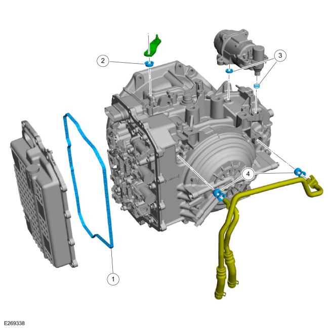
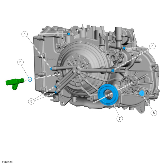
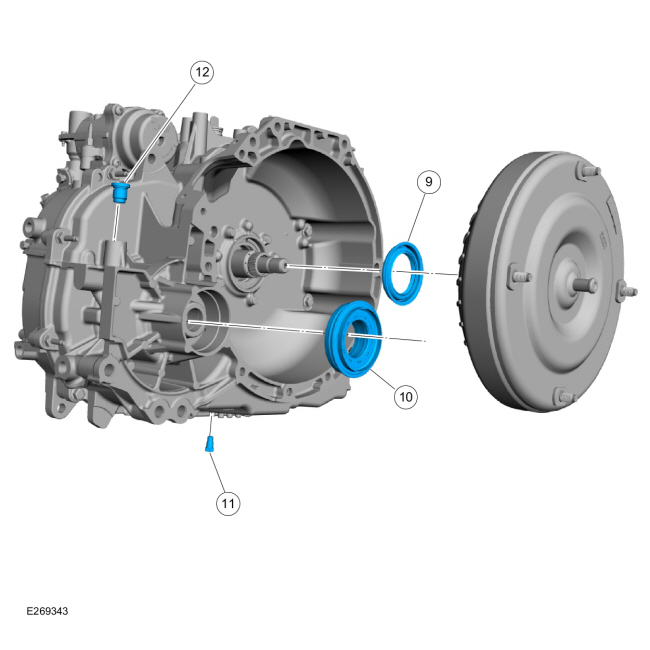
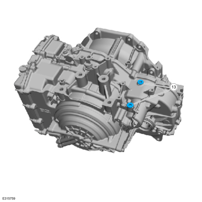
| Item | Description |
| 1 | Main control cover gasket |
| 2 | Manual control shaft seal |
| 3 | Auto-start-stop accumulator seal and O-rings (2 required) |
| 4 | Transmission fluid cooler tube seals (2 required) |
| 5 | Pressure test tap plug (6 required) |
| 6 | TSS/ISSA (Turbine Shaft Speed/Intermediate Shaft Speed) sensor assembly |
| 7 | LH halfshaft seal |
| 8 | Transmission fluid fill plug |
| 9 | Torque converter hub seal |
| 10 | RH halfshaft seal |
| 11 | Transmission fluid drain plug |
| 12 | Torque converter housing plug |
| 13 | Plug (2 required) non start/stop |
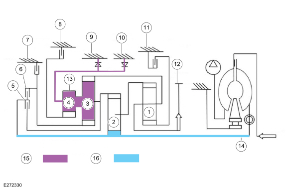
Park by Wire
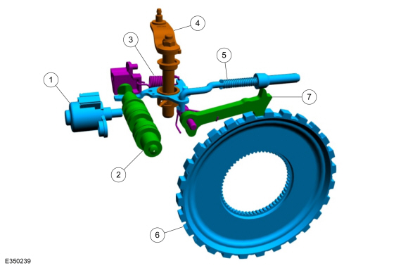
| Item | Description |
| 1 | Park lock solenoid |
| 2 | Park lock valve |
| 3 | Park return spring |
| 4 | Park override lever and shaft |
| 5 | Park Pawl Actuator rod |
| 6 | Park gear |
| 7 | Park pawl |
Park by Wire
- Uses a GSM with a rotary dial or push buttons in place of a mechanical shifter as the customer interface for selecting (P, R, N, D, M).
-
The transmission hydraulic controls are modified
using a park lock pawl valve connected to the park rod which unlocks and
locks the parking pawl from the carrier.
- Uses clutch C and F hydraulic pressure to push the system out of Park.
- Once out of Park, line pressure can continue to hold the system out of Park.
- A park lock pawl solenoid is used to allow the system to remain out of Park when the engine is not running.
- The dual TR sensors indicate the state of the Park system and are not used to determine customer selected range, which is now provided by the GSM .

 Description and Operation - A Clutch
A Clutch Exploded View
Item
Description
1
Snap ring
2
A (1, 2, 3, 4, 5) clutch pressure plate
3
A (1, 2, 3, 4, 5) clutch friction plates
4
A (1, 2, 3, 4, 5) clutch steel plates
5
A (1, 2, 3, 4, 5) clutch apply plate
6
Snap ring
7
A (1, 2, 3, 4, 5) clutch pis..
Other information:
Lincoln Corsair 2020-2025 Service Manual: Description and Operation - Accessory Drive - Component Location
Item Description 1 A/C compressor belt 2 Crankshaft pulley 3 Accessory drive belt 4 Accessory drive belt idler pulley 5 Accessory drive belt safety shield 6 Accessory drive belt tensioner 7 Coolant pump 8 Generator 9 Accessory drive bracket 10 A/C compressor ..
Lincoln Corsair 2020-2025 Service Manual: Removal and Installation - Windshield Washer Reservoir
Special Tool(s) / General Equipment Fluid Suction Gun Materials Name Specification Motorcraft® Premium Windshield Wash Concentrate with BitterantZC-32-B2 WSS-M14P19-A Removal NOTE: Removal steps in this procedure may contain installation details. Remove the retainers and the RH fill cowl side panel. Siphon the wind..
Categories
- Manuals Home
- 1st Generation Lincoln Corsair Owners Manual
- 1st Generation Lincoln Corsair Service Manual
- Auto Hold (IF EQUIPPED)
- Overhaul - Main Control Valve Body
- Head Up Display
- New on site
- Most important about car
Information on P Type Tires
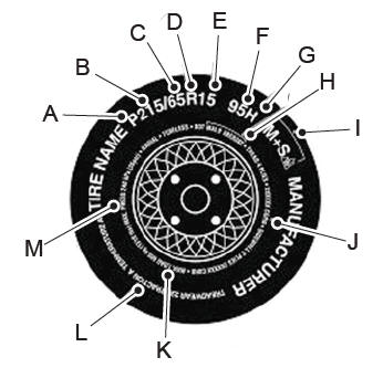
P215/65R15 95H is an example of a tire size, load index and speed rating. The definitions of these items are listed below. (Note that the tire size, load index and speed rating for your vehicle may be different from this example.)
P: Indicates a tire, designated by the Tire and Rim Association, that may be used for service on cars, sport utility vehicles, minivans and light trucks. Note: If your tire size does not begin with a letter this may mean it is designated by either the European Tire and Rim Technical Organization or the Japan Tire Manufacturing Association. 215: Indicates the nominal width of the tire in millimeters from sidewall edge to sidewall edge. In general, the larger the number, the wider the tire. 65: Indicates the aspect ratio which gives the tire's ratio of height to width. R: Indicates a radial type tire. 15: Indicates the wheel or rim diameter in inches. If you change your wheel size, you will have to purchase new tires to match the new wheel diameter. 95: Indicates the tire's load index. It is an index that relates to how much weight a tire can carry. You may find this information in your owner’s manual. If not, contact a local tire dealer.