Lincoln Corsair: Driveshaft / Removal and Installation - Rear Driveshaft
Special Tool(s) / General Equipment
| Flat Headed Screw Driver | |
| Punch | |
| Copper Hammer |
Removal
-
Remove the muffler and tailpipe.
Refer to: Muffler and Tailpipe (309-00B Exhaust System - 2.3L EcoBoost (199kW/270PS), Removal and Installation).
Refer to: Muffler and Tailpipe (309-00A Exhaust System - 2.0L EcoBoost (177kW/240PS) – MI4, Removal and Installation).
-
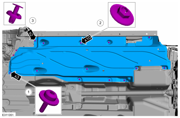
Remove the LH front air deflector.
-
Remove the screws and washers.
-
Remove the stamped nuts.
-
Remove the push pins.
-
Remove the screws and washers.
 |
-
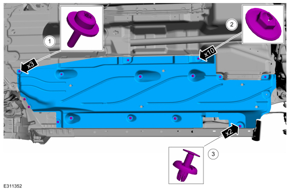
Remove the RH front air deflector.
-
Remove the screws and washers.
-
Remove the stamped nuts.
-
Remove the push pins.
-
Remove the screws and washers.
 |
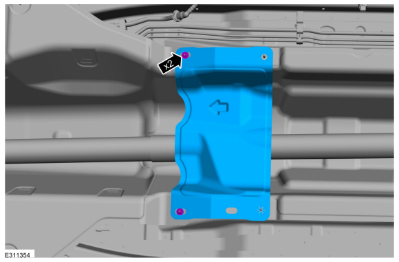
-
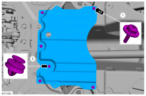
Remove the heat shield.
-
Remove the screws and washers.
-
Remove the push pin.
-
Remove the screws and washers.
 |
-
Remove the stamped nuts and the heat shield.
 |
-
NOTE: The installation step requires the aid of another technician.
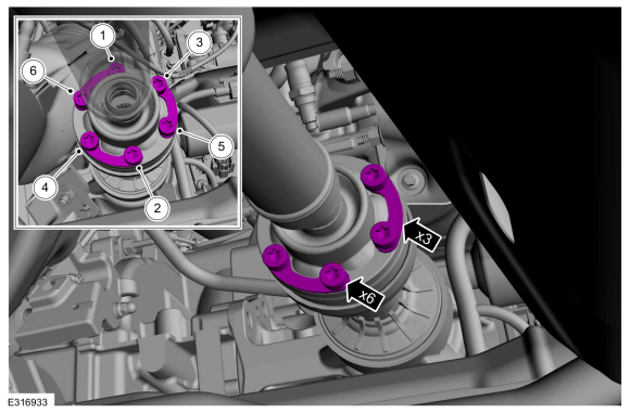
Remove and discard the driveshaft to PTU bolts and the retaining straps.
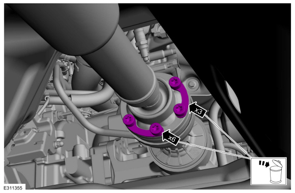 |
-
Separate the driveshaft from the PTU flange.
-
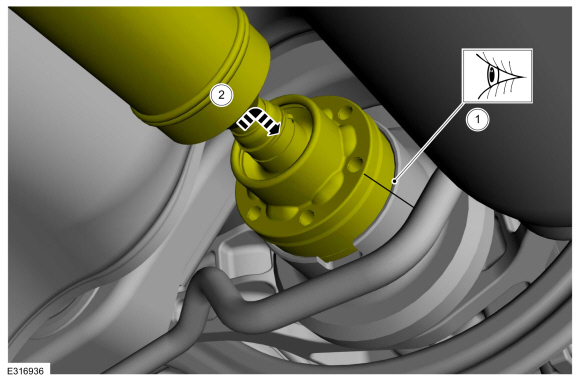
NOTE: Make sure that the component aligns with the installation mark.
Index-mark the driveshaft and PTU flange.
-
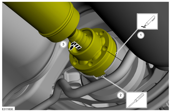
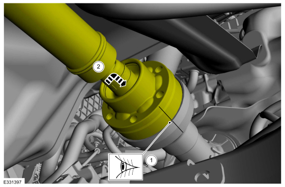
NOTICE: Do not remove driveshaft from the PTU flange by pulling on the driveshaft tube. Damage to the CV-joint can result.
NOTE: This is a tight fit, do not remove the CV flange from the PTU flange at this time.
Using general equipments, separate the driveshaft from the PTU flange.
Use the General Equipment: Punch
Use the General Equipment: Copper Hammer
-
NOTE: This step requires the aid of another technician.
Remove the driveshaft from the PTU flange.
-
 |
-
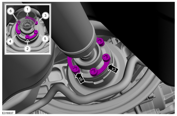
Remove and discard the driveshaft to RDU flange bolts and retaining straps.
 |
-
Separate the driveshaft from the drive pinion flange.
-
NOTE: Make sure that the component aligns with the installation mark.
Index-mark the driveshaft and RDU flange.
-
Using general equipment, separate the driveshaft from drive pinion flange.
Use the General Equipment: Flat Headed Screw Driver
-
Remove the driveshaft from the RDU flange.
-
 |
-
Remove the center bearing nuts.
 |
-
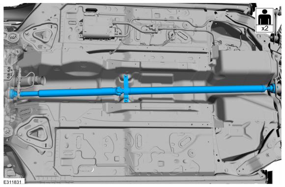
NOTE: Do not allow the angle of the driveshaft U-joint exceed 5 degrees.
NOTE: This step requires the aid of another technician.
With the help of an assistant, remove the driveshaft.
 |
Installation
-
NOTE: This step requires the aid of another technician.
With the help of an assistant, install the driveshaft.
|
-
Install the center bearing nuts.
Torque: 41 lb.ft (55 Nm)
|
-
-
Align the index-mark on the driveshaft and RDU flange.
-
Fit the driveshaft into the RDU flange.
-
Align the index-mark on the driveshaft and RDU flange.
 |
-
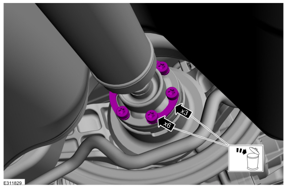
-
Install the new driveshaft to the RDU flange retaining straps and bolts.
-
Tighten the driveshaft to the RDU flange bolts in criss-cross pattern.
Torque: 26 lb.ft (35 Nm)
-
Install the new driveshaft to the RDU flange retaining straps and bolts.
 |
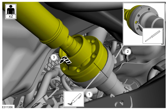
-
-
Align the index-mark on the driveshaft and PTU flange.
-
Fit the driveshaft into the drive pinion flange.
-
Align the index-mark on the driveshaft and PTU flange.
 |
-
-
Install the new driveshaft to the PTU flange retaining straps and bolts.
-
Tighten the driveshaft to the PTU flange bolts in criss-cross pattern.
Torque: 26 lb.ft (35 Nm)
-
Install the new driveshaft to the PTU flange retaining straps and bolts.
 |
-
Install the heat shield and the stamped nuts.
|
-
Install the heat shield.
-
Install the screws and washers.
-
Install the push pin.
-
Install the screws and washers.
|
-
Install the RH front air deflector.
-
Install the screws and washers.
-
Install the stamped nuts.
-
Install the push pins.
-
Install the screws and washers.
|
-
Install the LH front air deflector.
-
Install the screws and washers.
-
Install the stamped nuts.
-
Install the push pins.
-
Install the screws and washers.
|
-
Install the muffler and tailpipe.
Refer to: Muffler and Tailpipe (309-00B Exhaust System - 2.3L EcoBoost (199kW/270PS), Removal and Installation).
Refer to: Muffler and Tailpipe (309-00A Exhaust System - 2.0L EcoBoost (177kW/240PS) – MI4, Removal and Installation).
 General Procedures - Driveshaft Runout and Balancing
Special Tool(s) /
General Equipment
100-002
(TOOL-4201-C)
Holding Fixture with Dial Indicator Gauge
Inspection
NOTE:
Driveline vibration exhibits a higher frequency and lower
amplitude then high-speed shake...

Other information:
Lincoln Corsair 2020-2026 Owners Manual: Getting Assistance Outside the U.S. and Canada
Before exporting your vehicle to a foreign country, contact the appropriate foreign embassy or consulate. These officials can inform you of local vehicle registration regulations and where to find unleaded fuel or petrol/gas engines or the proper sulfur fuel for diesel engines. If you cannot find the proper fuel recommended for your vehicle, contact our Customer Relationship Center. The us..
Lincoln Corsair 2020-2026 Owners Manual: Steering
Electric Power Steering WARNING: The electric power steering system has diagnostic checks that continuously monitor the system. If a fault is detected, a message displays in the information display. Stop your vehicle as soon as it is safe to do so. Switch the ignition off. After at least 10 seconds, switch the ignition on and watch the information display for a steering system warning mes..
Categories
- Manuals Home
- 1st Generation Lincoln Corsair Owners Manual
- 1st Generation Lincoln Corsair Service Manual
- Selecting a Drive Mode. DRIVE MODES
- Overhaul - Main Control Valve Body
- Automatic Transmission - 8-Speed Automatic Transmission – 8F35/8F40
- New on site
- Most important about car
Keyless Starting
Note: The keyless starting system may not function if the key is close to metal objects or electronic devices such as cellular phones.
Note: A valid key must be located inside your vehicle to switch the ignition on and start the engine.
Ignition Modes