Lincoln Corsair Manuals

Lincoln Corsair: Power Steering / Diagnosis and Testing - Power Steering

Diagnostic Trouble Code (DTC) Chart

Diagnostics in this manual assume a certain skill level and knowledge of Ford-specific diagnostic practices.
REFER to: Diagnostic Methods (100-00 General Information, Description and Operation).


Module DTC Description Action
ABS C0051:23 Steering Wheel Position Sensor: Signal Stuck Low GO to Pinpoint Test AG
ABS C0051:27 Steering Wheel Position Sensor: Signal Rate Of Change Above Threshold GO to Pinpoint Test AG
ABS C0051:28 Steering Wheel Position Sensor: Signal Bias Level Out Of Range/Zero Adjustment Failure GO to Pinpoint Test AG
ABS C0051:29 Steering Wheel Position Sensor: Signal Invalid GO to Pinpoint Test AG
ABS C0051:54 Steering Wheel Position Sensor: Missing Calibration GO to Pinpoint Test AG
ABS C0051:62 Steering Wheel Position Sensor: Signal Compare Failure GO to Pinpoint Test AG
ABS C0051:64 Steering Wheel Position Sensor: Signal Plausibility Failure GO to Pinpoint Test AG
ABS C0051:67 Steering Wheel Position Sensor: Signal Incorrect After Event GO to Pinpoint Test AG
ABS C0051:82 Steering Wheel Position Sensor: Alive/Sequence Counter Incorrect/Not Updated GO to Pinpoint Test AG
ABS C0051:85 Steering Wheel Position Sensor: Signal Above Allowable Range GO to Pinpoint Test AG
ABS C0051:86 Steering Wheel Position Sensor: Signal Invalid GO to Pinpoint Test AG
ABS C0051:96 Steering Wheel Position Sensor: Component Internal Failure GO to Pinpoint Test AG
ABS C006B:00 Stability System Active Too Long: No Sub Type Information GO to Pinpoint Test AG
PSCM B1D23:4B Overheat Sensor: Over Temperature GO to Pinpoint Test BB
PSCM C1110:56 Power steering Calibration Data: Invalid/Incompatible Configuration GO to Pinpoint Test AA
PSCM C1B00:49 Steering Angle Sensor: Internal Electronic Failure GO to Pinpoint Test BF
PSCM C1B00:62 Steering Angle Sensor: Signal Compare Failure GO to Pinpoint Test BF
PSCM C200B:49 Steering Shaft Torque Sensor 1: Internal Electronic Failure GO to Pinpoint Test BG
PSCM C200B:62 Steering Shaft Torque Sensor 1: Signal Compare Failure GO to Pinpoint Test BG
PSCM C200D:49 Motor Rotation Angle Sensor: Internal Electronic Failure GO to Pinpoint Test BI
PSCM C200D:62 Motor Rotation Angle Sensor: Signal Compare Failure GO to Pinpoint Test BI
PSCM U0100:00 Lost Communication With ECM/PCM 'A': No Sub Type Information GO to Pinpoint Test AJ
PSCM U0121:00 Lost Communication With Anti-Lock Brake System (ABS) Control Module 'A': No Sub Type Information GO to Pinpoint Test AK
PSCM U0140:00 Lost Communication With Body Control Module: No Sub Type Information GO to Pinpoint Test AL
PSCM U0146:00 Lost Communication With Serial Data Gateway 'A': No Sub Type Information GO to Pinpoint Test AM
PSCM U0151:00 Lost Communication With Restraints Control Module: No Sub Type Information GO to Pinpoint Test AN
PSCM U0155:00 Lost Communication With Instrument Panel Cluster (IPC) Control Module: No Sub Type Information GO to Pinpoint Test AO
PSCM U0159:00 Lost Communication With Parking Assist Control Module 'A': No Sub Type Information GO to Pinpoint Test AP
PSCM U0212:00 Lost Communication With Steering Column Control Module: No Sub Type Information GO to Pinpoint Test AQ
PSCM U023A:00 Lost Communication With Image Processing Module A: No Sub Type Information GO to Pinpoint Test AR
PSCM U0401:00 Invalid Data Received from ECM/PCM A: No Sub Type Information GO to Pinpoint Test AS
PSCM U0415:00 Invalid Data Received from Anti-Lock Brake System (ABS) Control Module 'A': No Sub Type Information GO to Pinpoint Test AT
PSCM U0415:22 Invalid Data Received from Anti-Lock Brake System (ABS) Control Module 'A': Signal Amplitude Greater Than Maximum GO to Pinpoint Test AT
PSCM U0429:00 Invalid Data Received From Steering Column Control Module: No Sub Type Information GO to Pinpoint Test AU
PSCM U0447:00 Invalid Data Received From Serial Data Gateway 'A': No Sub Type Information GO to Pinpoint Test AV
PSCM U045A:00 Invalid Data Received From Parking Assist Control Module 'A': No Sub Type Information GO to Pinpoint Test AW
PSCM U053B:00 Invalid Data Received From Image Processing Module A: No Sub Type Information GO to Pinpoint Test AX
PSCM U2016:09 Control Module Main Software: Component Failures GO to Pinpoint Test BO
PSCM U2016:47 Control Module Main Software: Watchdog/Safety µC Failure GO to Pinpoint Test BO
PSCM U2016:48 Control Module Main Software: Supervision Software Failure GO to Pinpoint Test BO
PSCM U2016:57 Control Module Main Software: Invalid/Incompatible Software Component GO to Pinpoint Test BO
PSCM U2016:66 Control Module Main Software: Signal Has Too Many Transitions/Events GO to Pinpoint Test BO
PSCM U2016:94 Control Module Main Software: Unexpected Operation GO to Pinpoint Test BO
PSCM U2100:00 Initial Configuration Not Complete: No Sub Type Information GO to Pinpoint Test BQ
PSCM U2300:55 Central Configuration: Not Configured GO to Pinpoint Test AB
PSCM U3000:05 Control Module: System Programming Failures GO to Pinpoint Test B
PSCM U3000:42 Control Module: General Memory Failure GO to Pinpoint Test B
PSCM U3000:49 Control Module: Internal Electronic Failure GO to Pinpoint Test B
PSCM U3000:4B Control Module: Over Temperature GO to Pinpoint Test BE
PSCM U3000:61 Control Module: Signal Calculation Failure GO to Pinpoint Test B
PSCM U3000:66 Control Module: Signal Has Too Many Transitions/Events GO to Pinpoint Test B
PSCM U3001:68 Control Module Improper Shutdown Performance: Event Information GO to Pinpoint Test BD
PSCM U3003:16 Battery Voltage: Circuit Voltage Below Threshold GO to Pinpoint Test BC
PSCM U3003:17 Battery Voltage: Circuit Voltage Above Threshold GO to Pinpoint Test BC
PSCM U3003:68 Battery Voltage: Event Information GO to Pinpoint Test BC

Global Customer Symptom Code (GCSC) Chart

Diagnostics in this manual assume a certain skill level and knowledge of Ford-specific diagnostic practices.
REFER to: Diagnostic Methods (100-00 General Information, Description and Operation).


Symptom Action
Stop/Steer/Ride > Steering/Steering Wheel > Feel/Wander/Pull > Intermittent GO to Pinpoint Test D
Stop/Steer/Ride > Steering/Steering Wheel > Performance > Intermittent GO to Pinpoint Test D
Stop/Steer/Ride > Fluids > Steering > Visible Leak GO to Pinpoint Test BA
Stop/Steer/Ride > Noise > Stopping > High Speed GO to Pinpoint Test AI
Stop/Steer/Ride > Noise > Stopping > Low Speed GO to Pinpoint Test AF
Stop/Steer/Ride > Noise > Stopping > Low Speed GO to Pinpoint Test AI
Stop/Steer/Ride > Noise > Steering > Intermittent GO to Pinpoint Test AF
Stop/Steer/Ride > Noise > Steering > Over Bump GO to Pinpoint Test AC
Stop/Steer/Ride > Noise > Steering > Low Speed GO to Pinpoint Test AE
Stop/Steer/Ride > Noise > Steering > While Turning GO to Pinpoint Test AD
Stop/Steer/Ride > Noise > Steering > While Turning GO to Pinpoint Test AE
Stop/Steer/Ride > Noise > Front > Over Bump GO to Pinpoint Test AC
Stop/Steer/Ride > Noise > Front > Low Speed GO to Pinpoint Test AF
Stop/Steer/Ride > Vibration > Steering > Intermittent GO to Pinpoint Test E

Symptom Chart(s)

Symptom Chart: Steering System and NVH

  • Diagnostics in this manual assume a certain skill and knowledge of Ford-specific diagnostic practices.
    REFER to: Diagnostic Methods (100-00 General Information, Description and Operation).
  • NVH symptoms should be identified using the diagnostic tools available. For a list of these tools, an explanation of their uses and a glossary of common terms,
    REFER to: Noise, Vibration and Harshness (NVH) (100-04 Noise, Vibration and Harshness, Description and Operation).
    . Since it is possible any one of multiple systems may be the cause of a symptom, it may be necessary to use a process of elimination type diagnostic approach to pinpoint the responsible system. If this is not the causal system for the symptom, REFER to: Noise, Vibration and Harshness (NVH) (100-04 Noise, Vibration and Harshness, Description and Operation).
    for the next likely system and continue diagnostics.
  • If equipped, the Lane Keeping System (LKS) can interfere with accurate EPAS diagnostics. Disable the Lane Keeping System (LKS) before test driving the vehicle to diagnose EPAS concerns. For information on disabling the Lane Keeping System (LKS), refer to Owner's Literature.

There are multiple conditions (overheating protection, high voltage, low voltage, etc.) which result in limited or reduced assist from the EPAS system. Address all existing PSCM Diagnostic Trouble Codes (DTCs) prior to diagnosing any assist symptoms.

Condition Actions
Message center displays STEERING FAULT SERVICE NOW   GO to Pinpoint Test M
Message center displays STEERING ASSIST FAULT SERVICE REQUIRED   GO to Pinpoint Test J
Message center displays STEERING LOSS STOP SAFELY   GO to Pinpoint Test Z
ABS Module DTC C0051:XX Steering Angle Concerns With The PSCM   GO to Pinpoint Test AG
DTC U0131:XX A module cannot communicate with the PSCM   GO to Pinpoint Test C
DTC U0420:XX Invalid Data Received From The PSCM   GO to Pinpoint Test BL
The PSCM cannot communicate with the diagnostic scan tool   GO to Pinpoint Test G
ASSIST - Open PSCM Fuse(s)   GO to Pinpoint Test A
ASSIST - Unable to replicate customers intermittent assist concern during a test drive   GO to Pinpoint Test F
LEAKING - Steering gear appears to be leaking fluid   GO to Pinpoint Test BA
NOISE - During acceleration (tip in) or deceleration (tip out) may occur with braking   GO to Pinpoint Test AF
NOISE - During braking   GO to Pinpoint Test AI
NOISE - Driving straight on smooth roads   GO to Pinpoint Test L
NOISE - Over bumps, rough roads, dips, depressions or when entering a driveway   GO to Pinpoint Test AC
NOISE - Turning at slow speeds or during parking lot maneuvers   GO to Pinpoint Test AE
NOISE - noticed more in the interior   GO to Pinpoint Test AD
STEERING - Excessive steering wheel play   GO to Pinpoint Test R
STEERING - Lack of assist or inconsistent assist   GO to Pinpoint Test BK
STEERING - Poor returnability or sticky steering or binding   GO to Pinpoint Test I
STEERING - Steering system pull, drift or wander   GO to Pinpoint Test H
STEERING WHEEL - Steering wheel is off center   GO to Pinpoint Test BC

Pinpoint Tests


PINPOINT TEST A: OPEN PSCM (POWER STEERING CONTROL MODULE) FUSE(S)

Refer to Wiring Diagrams Cell 43 for schematic and connector information.

Normal Operation and Fault Conditions

There are 2 power sources for the PSCM , the high current power steering fuse, and the low current power steering fuse. Refer to the wiring diagrams to review the PSCM circuit for both the high current and low current fuse locations as well as the associated power and ground wiring. Open power steering fuse can occur when the power or ground wiring is shorted against another component or water intrusion in the respective connectors or connections.

Possible Sources

  • Fuse(s)
  • Wiring, terminals or connectors
  COMPLETE THE FDRS GUIDED ROUTINE
  • NOTE: This procedure must be completed using FDRS. Do not clear DTCs until the FDRS procedure has completed.
      To complete the diagnosis, navigate to the FDRS Guided Routine tab and carry out the procedure Electronic Power Assist Steering (EPAS) Invalid or Missing Controller Area Network (CAN) Data.

PINPOINT TEST B: PSCM (POWER STEERING CONTROL MODULE) DTC (DIAGNOSTIC TROUBLE CODE) U3000 CONTROL MODULE
Introduction
Refer to Wiring Diagrams Cell 43 for schematic and connector information.

Normal Operation and Fault Conditions

REFER to: Power Steering - System Operation and Component Description (211-02 Power Steering, Description and Operation).

Description

    Description

  • The PSCM is self monitoring and performs self tests at specific intervals (initial power up, power down, during normal operation, ect.) Each self test requires the voltage supply to the PSCM to be at or above a specific level (above 6 volts, above 9 volts, between 10 and 17 volts, ect.) for the test to take place. If one or more of the self tests should fail, the module sets one or more Diagnostic Trouble Codes (DTCs).

Pinpoint Test Applicability

    Pinpoint Test Applicability

  • This test applies to PSCM DTC U3000:xx Diagnostic Trouble Codes (DTCs) except for U3000:4B. This test does not apply to any other module except the PSCM .

DTC Diagnostic Strategy

    DTC Diagnostic Strategy

  • If the module DTC list results in a large number of Diagnostic Trouble Codes (DTCs), diagnose all module hard faults first (C102D, C1B00, C200B, C200C, C200D, U2011 and U3000) before diagnosing any network faults (lost communication or invalid data). If voltage concern Diagnostic Trouble Codes (DTCs) are present, diagnose those after any module hard faults and before any network faults. Diagnose all current and active Diagnostic Trouble Codes (DTCs) before diagnosing any historic Diagnostic Trouble Codes (DTCs).

Pinpoint Test Purpose

    Pinpoint Test Purpose

  • To verify PSCM U3000:XX is present and provide diagnostics if DTC U3000:XX is currently present and active in the PSCM .

Diagnostic Aids

    Diagnostic Aids

  • For DTC U3000:42, steering assist is not affected and there is no warning in the message center. The PSCM may transmit an invalid steering angle message over the HS-CAN .
  • For DTC U3000:49, during the ignition cycle the DTC initially sets, the PSCM enters limp home mode and steering assist is gradually reduced until the PSCM enters manual mode. The PSCM sends a message to the IPC to display the STEERING ASSIST FAULT SERVICE REQUIRED in the message center.
  • During the next ignition cycle after the DTC sets, If the PSCM is not already in manual mode the PSCM removes steering assist and enters manual mode. The module also transmits an invalid steering angle message over the HS-CAN and sends a message to the IPC to display the STEERING ASSIST FAULT SERVICE REQUIRED in the message center.
  • The presence of DTC U3000:49 prevents the optional steering features; active park assist, Lane Keeping Assist (LKA) and Lane Centering Assist (LCA) from activating. If the DTC sets during an assist event, the event is terminated and the assist system is deactivated.

DTC Fault Trigger Conditions

DTC Description Fault Trigger Condition
PSCM U3000:05 Control Module: System Programming Failures If an internal error is detected in the PSCM hardware, DTC U3000:05 is set.
PSCM U3000:42 Control Module: General Memory Failure This DTC sets if the PSCM detects an internal memory data error during the data plausibility check.
PSCM U3000:49 Control Module: Internal Electronic Failure If any time during normal operation with more than 10 volts supplied to the PSCM , the module detects a software or internal hardware error, DTC U3000:49 is set.
PSCM U3000:61 Control Module: Signal Calculation Failure This DTC sets if the PSCM detects a steering sensor error during the data plausibility check.
PSCM U3000:66 Control Module: Signal Has Too Many Transitions/Events If the PSCM detects the fault mitigation counter has exceeded a pre-set limit, DTC U3000:66 is set.

Possible Sources

  • Heat shield missing
  • Steering column internal failure
  • Incorrect EPAS column installed
  • Heavy loads on the EPAS column
  • Excessive ambient temperatures

Visual Inspection and Pre-checks

  • This DTC sets when the PSCM internal self tests detect a software or hardware internal error. This can be to internal faults in the PSCM or from water getting inside the PSCM . For additional fault setting information, refer to the PSCM DTC Chart.
PINPOINT TEST C: DTC (DIAGNOSTIC TROUBLE CODE) U0131:XX A MODULE CANNOT COMMUNICATE WITH THE PSCM (POWER STEERING CONTROL MODULE)

Possible Sources

  • Fuse(s)
  • Wiring, terminals or connectors
  • HS-CAN concern
  • PSCM

Visual Inspection and Pre-checks

  • Workshop Manual diagnostics for another module not communicating with the PSCM must be carried out prior to entering this test.
  COMPLETE THE FDRS GUIDED ROUTINE
  • NOTE: This procedure must be completed using FDRS. Do not clear DTCs until the FDRS procedure has completed.
      To complete the diagnosis, navigate to the FDRS Guided Routine tab and carry out the procedure Electronic Power Assist Steering (EPAS) Invalid or Missing Controller Area Network (CAN) Data.

PINPOINT TEST D: UNABLE TO REPLICATE CUSTOMERS INTERMITTENT ASSIST CONCERN DURING A TEST DRIVE

NOTE: Customers may report an intermittent power steering concern that may not replicate during a test drive session. TSB , SSM or Diagnostic Trouble Codes (DTCs) may exist indicating the likely root cause. Retrieve all Diagnostic Trouble Codes (DTCs) for the vehicle, as well as TSB , SSM .

Normal Operation and Fault Conditions

there are 2 power sources for the PSCM , the high current power steering fuse, and the low current power steering fuse. Refer to the wiring diagrams to review the PSCM circuit for both the high current and low current fuse locations as well as the associated power and ground wiring. Open power steering fuse can occur when the power or ground wiring is shorted against another component or water intrusion in the respective connectors or connections.

REFER to: Power Steering - System Operation and Component Description (211-02 Power Steering, Description and Operation).

DTC Diagnostic Strategy

    DTC Diagnostic Strategy

  • If lost communication or voltage Diagnostic Trouble Codes (DTCs) exist in the PSCM or other vehicle modules, possible source can be fuse(s) or wiring, terminals, or connectors
  • If Diagnostic Trouble Codes (DTCs) other than lost communication or voltage exist in the PSCM or other vehicle modules, the possible source can be an internal fault in the PSCM or other vehicle modules.
  • If no Diagnostic Trouble Codes (DTCs) are present in the PSCM or other vehicle modules, the concern could be addressed by a service article such as a TSB , GSB , SSM , or FSA .

Possible Sources

  • Fuse(s)
  • Wiring, terminals or connectors
  • PSCM internal fault
  • Internal fault in other module(s) on the CAN
D1 CHECK THE DIAGNOSTIC TROUBLE CODES (DTCS) FROM ALL MODULES
  • Ignition ON.
  • Using a diagnostic scan tool, retrieve the Continuous Memory Diagnostic Trouble Codes (CMDTCs) from all modules.

Are Diagnostic Trouble Codes (DTCs) present in the PSCM or any other modules?
Yes DIAGNOSE the Diagnostic Trouble Codes (DTCs) in the PSCM and other vehicle modules.
For the PSCM , REFER to the DTC Chart in this section.
For other vehicle modules, REFER to the Master DTC Chart.
No CHECK OASIS for any applicable service articles: TSB , GSB , SSM or FSA . If a service article exists for this concern, DISCONTINUE this test and FOLLOW the service article instructions. If there are no Diagnostic Trouble Codes (DTCs) present and there are no service articles associated with this concern and the concern cannot be verified, RETURN the vehicle to the customer.

PINPOINT TEST E: STEERING WHEEL VIBRATES OR RESISTS TURNING

Normal Operation and Fault Conditions

Description

    Description

  • The steering wheel can vibrate or shake as well as resist turning into the next lane when the turn signals are not used to change lanes. This may be a normal operation of the Lane Keeping Assist feature.
  • .

REFER to: Lane Keeping System - System Operation and Component Description (419-07 Lane Keeping System, Description and Operation).

REFER to: Power Steering - System Operation and Component Description (211-02 Power Steering, Description and Operation).

Pinpoint Test Applicability

    Pinpoint Test Applicability

  • This test applies to the following diagnostic concerns:
  • Steering wheel vibrates or resists turning

This test DOES NOT apply to any other DTC or symptom.

Diagnostic Strategy

    Diagnostic Strategy

  • Determine if the vehicle is equipped with the Lane Keeping Assist feature and educate the customer how the feature is activated, de-activated and properly used. Verify the vibration and turning resistance is no longer present when the Lane Keeping Assist feature is de-activated.
  • Refer to the following sources of information on the PTS website:
  • Owner's Literature - REFER to DRIVING AIDS
  • Owner's Literature, Quick Reference Guide - REFER to FUNCTION
  • Lane Keeping Reference Guide (all vehicles)

Possible Sources

  • Normal operation of the Lake Keeping System
Diagnostic steps are not provided for this symptom or DTC.  REFER to: Diagnostic Methods (100-00 General Information, Description and Operation).
PINPOINT TEST F: UNABLE TO REPLICATE CUSTOMERS INTERMITTENT ASSIST CONCERN DURING A TEST DRIVE

NOTE: Customers may report an intermittent power steering concern that may not replicate during a test drive session. TSB , SSM or Diagnostic Trouble Codes (DTCs) may exist indicating the likely root cause. Retrieve all Diagnostic Trouble Codes (DTCs) for the vehicle, as well as TSB , SSM .


Refer to Wiring Diagrams Cell 43 for schematic and connector information.

Normal Operation and Fault Conditions

there are 2 power sources for the PSCM , the high current power steering fuse, and the low current power steering fuse. Refer to the wiring diagrams to review the PSCM circuit for both the high current and low current fuse locations as well as the associated power and ground wiring. Open power steering fuse can occur when the power or ground wiring is shorted against another component or water intrusion in the respective connectors or connections.

Possible Sources

  • Fuse(s)
  • Wiring, terminals or connectors
  COMPLETE THE FDRS GUIDED ROUTINE
  • NOTE: This procedure must be completed using FDRS. Do not clear DTCs until the FDRS procedure has completed.
      To complete the diagnosis, navigate to the FDRS Guided Routine tab and carry out the procedure Electronic Power Assist Steering (EPAS) Invalid or Missing Controller Area Network (CAN) Data.

PINPOINT TEST G: THE PSCM (POWER STEERING CONTROL MODULE) CANNOT COMMUNICATE WITH THE DIAGNOSTIC SCAN TOOL

Possible Sources

  • Fuse(s)
  • Wiring, terminals or connectors
  • HS-CAN concern
  • PSCM
  COMPLETE THE FDRS GUIDED ROUTINE
  • NOTE: This procedure must be completed using FDRS. Do not clear DTCs until the FDRS procedure has completed.
      To complete the diagnosis, navigate to the FDRS Guided Routine tab and carry out the procedure Electronic Power Assist Steering (EPAS) Invalid or Missing Controller Area Network (CAN) Data.

PINPOINT TEST H: STEERING WHEEL IS OFF CENTER, STEERING SYSTEM PULL, DRIFT OR WANDER
Introduction

Normal Operation and Fault Conditions

REFER to: Power Steering - System Operation and Component Description (211-02 Power Steering, Description and Operation).

The EPAS system is designed to compensate for some steering issues (drift, pull, wander, etc.). However, if the steering issue is severe enough, the condition or symptom may become noticeable to the driver.

The system starts compensating when vehicle speed exceeds 40 km/h (25 mph) and the vehicle is traveling straight. The system compensates on any road crown condition; however, some amount of pull is present during, and shortly after, quick lane transitions. After driving straight on a constant road crown with both hands on the steering wheel for at least 45 seconds, the pull condition can be assessed. The system does not compensate when turning at low speeds. For the system to compensate, the driver's hands must remain on the steering wheel.

Drift describes what a vehicle with this condition does with the hands off the steering wheel. A vehicle-related drift, on a flat road, can cause a consistent deviation from the straight-ahead path and require constant steering input in the opposite direction to counteract the effect. Drift can be induced by conditions external to the vehicle, such as wind or road camber.

Pull is described as a tugging sensation on the steering wheel felt by the driver, which must be overcome to keep the vehicle going straight.

Wander is the tendency of the vehicle to require frequent, random left and right steering wheel corrections to maintain a straight path down a level road.

Possible Sources

  • Alignment
  • Tires
  • Steering gear mounts
  • Steering column shaft U-joints
  • Steering column
  • Suspension components
  • Steering gear
PINPOINT TEST I: POOR RETURNABILITY OR STICKY STEERING
Introduction
Refer to Wiring Diagrams Cell 43 for schematic and connector information.

Normal Operation and Fault Conditions

REFER to: Power Steering - System Operation and Component Description (211-02 Power Steering, Description and Operation).

With a fully charged battery and the ignition ON, the EPAS system provides adequate assist to maneuver the vehicle and return to the straight-ahead position with little difficulty. The assist provided by the EPAS system should be smooth and consistent at all times. The steering and suspension components should be free of any binding conditions and should not interfere with the steering assist provided by the EPAS system.

If the steering wheel is held at the end of travel for more than 2 seconds, the level of assistance is noticeably reduced by the EPAS system. This is a normal condition programmed into the PSCM to protect the system from permanent damage.

Poor returnability or sticky steering is used to describe the poor return of the steering wheel to center after a turn or steering correction is completed.

Possible Sources

  • Fuses
  • Wiring, terminals or connectors
  • Under inflated or mismatched tires
  • Alignment
  • Binding suspension components
  • Binding steering gear
  • Binding steering gear bearings
  • Binding steering column shaft dash panel seal
  • Binding lower steering column shaft coupling or U-joint
  • Outer tie-rod ends
  • Inner tie rods
  • Loose, worn or damaged steering linkage
  • Steering gear internal failure
  • EPAS column internal failure

Visual Inspection and Pre-checks

  • Make sure the vehicle battery terminals and cables are free of any corrosion and other contaminants.
  • Make sure PSCM fuses in the BJB are OK.
  • Make sure there are no obvious loose, worn, damaged or binding suspension components.
PINPOINT TEST J: MESSAGE CENTER DISPLAYS STEERING ASSIST FAULT SERVICE REQUIRED

NOTE:

  • This message appears when a condition has been detected in the EPAS system requiring the PSCM to disable the system (remove assist) to help prevent the system from sustaining any possible damage. This message (and related symptom) may be cleared when the ignition key is cycled and may not be present at the time of diagnosis.
  • This message appears if a condition exists has been detected in the EPAS system requiring the PSCM to immediately reduce steering assist, gradually reduce assist or disable assist completely to help prevent the system from sustaining any possible damage. This message (and related symptom) may be cleared when the ignition key is cycled and may not be present at the time of diagnosis.

Refer to Wiring Diagrams Cell 43 for schematic and connector information.

Possible Sources

Diagnostic steps are not provided for this symptom or DTC.  REFER to: Diagnostic Methods (100-00 General Information, Description and Operation).
PINPOINT TEST L: FRONT END NOISE - DRIVING STRAIGHT ON SMOOTH ROADS
Introduction

NOTE:

  • Wheel hub bearings can produce noise after achieving 56 km/h (35 mph) while driving straight if they are worn.
  • Front end noises while driving straight involve parts which rotate continuously while the road wheels are rotating. Typically not a steering gear.
  • Noises can also be caused by loose or un-retained parts affected by wind.

Possible Sources

  • Possible rotating sources:
  • Axle shafts or halfshafts
  • Carrier bearing (noise is typically felt through the console)
  • Drive shafts
  • Transfer case assembly (if equipped)
  • Wheel hub and wheel bearings (typically higher speeds)
  • Possible Wind Sources:
  • Air dams
  • Heat shields
  • Radiator ducts or shields
  • Wheel well splash shields
PINPOINT TEST R: EXCESSIVE STEERING WHEEL PLAY
Introduction

Normal Operation and Fault Conditions

REFER to: Power Steering - System Operation and Component Description (211-02 Power Steering, Description and Operation).

Excessive steering wheel free play is a condition in which there is too much steering wheel movement before the wheels move. The EPAS system is designed to compensate for some steering wheel free play, however a small amount of steering wheel free play is considered normal.

Possible Sources

  • Steering column shaft U-joints
  • Loose, damaged or worn inner or outer tie rods
  • Steering gear internal failure
  • EPAS column internal failure
PINPOINT TEST M: MESSAGE CENTER DISPLAYS STEERING FAULT SERVICE NOW

NOTE:

  • This message appears when a condition has been detected requiring the PSCM to disable the system (remove assist) to help prevent the system from sustaining any possible damage. This message (and related symptom) may be cleared when the ignition is cycled and may not be present at the time of diagnosis or may not clear until the condition is repaired.
  • This message appears if a condition exists (high friction for example) putting extra load on the EPAS system. Steering assist remains for the current ignition cycle. If the ignition is turned OFF and then back ON, STEERING FAULT SERVICE NOW appears in the message center and steering assist is removed until the condition is repaired.

Refer to Wiring Diagrams Cell 43 for schematic and connector information.

Possible Sources

Diagnostic steps are not provided for this symptom or DTC.  REFER to: Diagnostic Methods (100-00 General Information, Description and Operation).
PINPOINT TEST BA: STEERING GEAR APPEARS TO BE LEAKING FLUID
Introduction

Normal Operation and Fault Conditions

REFER to: Power Steering - System Operation and Component Description (211-02 Power Steering, Description and Operation).

Steering Gears That Appear To Be Leaking Power Steering Fluid

    Steering Gears That Appear To Be Leaking Power Steering Fluid

  • EPAS gears are not filled with power steering fluid.
  • Only HPAS gears are filled with power steering fluid.
  • Only HPAS gears can leak power steering fluid.

Pinpoint Test Purpose

    Pinpoint Test Purpose

  • To provide diagnostic direction about external fluids leaking onto EPAS gears and components.

External Sources Of Fluids

    External Sources Of Fluids

  • Engine coolant
  • Engine oil
  • Transmission fluid
  • Brake fluid
  • Fluid from nearby reservoir bottles

Possible Sources

  • External fluid source dripping or leaking onto the steering gear
PINPOINT TEST BB: B1D23:4B
Introduction
Refer to Wiring Diagrams Cell 43 for schematic and connector information.

Normal Operation and Fault Conditions

REFER to: Power Steering - System Operation and Component Description (211-02 Power Steering, Description and Operation).

Description

    Description

  • The PSCM uses a thermistor to monitor the internal temperature of the EPAS gear. This DTC appearing by itself does not indicate a fault condition in the steering system. Diagnose all other EPAS Diagnostic Trouble Codes (DTCs) before diagnosing B1D23:4B.

Pinpoint Test Applicability

    Pinpoint Test Applicability

  • This test applies to PSCM DTC B1D23:4B only. It does not apply to any other module except PSCM .

DTC Diagnostic Strategy

    DTC Diagnostic Strategy

  • If the module DTC list results in a large number of Diagnostic Trouble Codes (DTCs), diagnose all module hard faults first (C102D, C1B00, C200B, C200C, C200D, U2011 and U3000) before diagnosing any network faults (lost communication or invalid data). If voltage concern Diagnostic Trouble Codes (DTCs) are present, diagnose those after any module hard faults and before any network faults.

Pinpoint Test Purpose

    Pinpoint Test Purpose

  • This test inspects the steering gear and the surrounding engine compartment for hot components, missing heat shields or a damaged steering gear housing creating an opening into the steering gear.

Diagnostic Aids

    Diagnostic Aids

  • The PSCM reporting only DTC B1D23:4B does not indicate a fault in the PSCM . It indicates an over-temperature condition due to ambient conditions or a heavy load on the EPAS system. An example of a heavy load would be multiple parking lot maneuvers over a short duration of time with low tire pressure or towing for long distances followed by multiple parking maneuvers.
  • The thermistor used by the PSCM is calibrated for 80ºC (176ºF) and as ambient temperature decreases, so does the accuracy of the sensor. At room temperature and lower, the sensor is +/- 20ºC (68ºF).
  • The presence of DTC B1D23:4B prevents the optional steering features; active park assist, Lane Keeping Assist (LKA) and Lane Centering Assist (LCA) from activating. If the DTC sets during an assist event, the event is terminated and the assist feature is deactivated.

DTC Fault Trigger Conditions

DTC Description Fault Trigger Condition
PSCM B1D23:4B Overheat Sensor: Over Temperature This DTC sets if the internal temperature of the EPAS gear exceeds a predetermined threshold. This is most likely due to high ambient temperature conditions, heavy loads on the steering gear, or a damaged PSCM housing allowing heat into the steering gear. Consult the DTC Index for additional information if needed.

Possible Sources

  • Heavy loads on the steering gear
  • Excessive ambient temperatures
  • PSCM

Visual Inspection and Pre-checks

  • Refer to Steering GSB for additional connector and wiring inspection tips.
PINPOINT TEST BC: U3003:16, U3003:17, OR U3003:68
Introduction
Refer to Wiring Diagrams Cell 43 for schematic and connector information.

Normal Operation and Fault Conditions

REFER to: Power Steering - System Operation and Component Description (211-02 Power Steering, Description and Operation).

Description

    Description

  • The PSCM monitors the voltage supplied by the 12 volt battery and charging system and sets the appropriate DTC when necessary.

Pinpoint Test Applicability

    Pinpoint Test Applicability

  • This test applies to PSCM DTC U3003:16, U3003:17, or U3003:68 only. It does not apply to any other module except PSCM .

DTC Diagnostic Strategy

    DTC Diagnostic Strategy

  • If the module DTC list results in a large number of Diagnostic Trouble Codes (DTCs), diagnose all module hard faults first (C102D, C1B00, C200B, C200C, C200D, U2011 and U3000) before diagnosing any network faults (lost communication or invalid data). If voltage concern Diagnostic Trouble Codes (DTCs) are present, diagnose those after any module hard faults and before any network faults.

Pinpoint Test Purpose

    Pinpoint Test Purpose

  • This test verifies the PSCM fuses in the BJB and the high current BJB are OK, the PSCM wiring harness power and ground connections are OK. The test also verifies the charging system and battery state of charge.

Diagnostic Aids

    Diagnostic Aids

  • For some instances the message center may display: STEERING ASSIST FAULT SERVICE REQUIRED. This does not indicate a concern with the PSCM if only DTC U3003:XX is present. The 12 volt battery health should be evaluated.
  • The PSCM reporting only DTC U3003:16, U3003:17 or U3003:68 does not indicate a concern with the PSCM . DO NOT install a new EPAS assembly or PSCM if one or more of these Diagnostic Trouble Codes (DTCs) is set.
  • The presence of DTC U3003:16, U3003:17, U3003:18 or U3003:68 prevents the optional steering features; Active Park Assist, Lane Keeping Assist (LKA) and Lane Centering Assist (LCA) feature from activating. If the DTC sets during an assist event, the event is terminated and the assist feature is deactivated. The presence of one of these Diagnostic Trouble Code's may also result in heavier than usual steering efforts.
  • When DTC U3003:16 is set, the PSCM reduces power steering assist to a predetermined current draw. If EPAS operation exceeds this current limit, the PSCM continues to reduce steering assist until the current draw is below the limit or until assist is removed completely.

DTC Fault Trigger Conditions

DTC Description Fault Trigger Condition
PSCM U3003:16 Battery Voltage: Circuit Voltage Below Threshold If the voltage supply to the PSCM falls below 9 volts with the ignition ON and the engine ready indicator illuminated for more than 5 seconds (hybrid vehicles) or engine speed above 500 RPM ( all other vehicles), then DTC U3003:16 is set.
PSCM U3003:17 Battery Voltage: Circuit Voltage Above Threshold If the voltage supply to the PSCM exceeds 18 volts with the ignition ON, then DTC U3003:17 is set. DTC U3003:17 can also set if the vehicle has been recently jump started or the battery has been recently charged.
PSCM U3003:68 Battery Voltage: Event Information If the voltage supply to the PSCM is less than 11.8 volts or if the charging system warning indicator is illuminated with the ignition ON and the PSCM awake, then DTC U3003:68 is set.

Possible Sources

  • Fuses
  • Wiring, terminals or connectors
  • Charging system concern
  • 12 volt Battery
  • PSCM

Visual Inspection and Pre-checks

  • Make sure the vehicle battery terminals and cables are free of any corrosion and other contaminants.
  • Make sure the vehicle battery terminals are tightened to their correct torque specifications.
  • Make sure all PSCM fuses in the BJB and high current BJB are OK.
  • Refer to Steering GSB for additional connector and wiring inspection tips.
PINPOINT TEST BD: PSCM (POWER STEERING CONTROL MODULE) DTC (DIAGNOSTIC TROUBLE CODE) U3001:68
Introduction
Refer to Wiring Diagrams Cell 43 for schematic and connector information.

Normal Operation and Fault Conditions

REFER to: Power Steering - System Operation and Component Description (211-02 Power Steering, Description and Operation).

Description

    Description

  • When the ignition is set to OFF, the PSCM remains powered up for a short period of time to store data in memory. When the ignition is set to ON, the PSCM retrieves this information and if the information is missing or corrupted a DTC is set.

Pinpoint Test Applicability

    Pinpoint Test Applicability

  • This test applies to PSCM DTC U3001:68 only. This test does not apply to any other module except the PSCM .

DTC Diagnostic Strategy

    DTC Diagnostic Strategy

  • If the module DTC list results in a large number of Diagnostic Trouble Codes (DTCs), diagnose all module hard faults first (C102D, C1B00, C200B, C200C, C200D, U2011 and U3000) before diagnosing any network faults (lost communication or invalid data). If voltage concern Diagnostic Trouble Codes (DTCs) are present, diagnose those after any module hard faults and before any network faults. Diagnose all current and active Diagnostic Trouble Codes (DTCs) before diagnosing any historic Diagnostic Trouble Codes (DTCs).

Pinpoint Test Purpose

    Pinpoint Test Purpose

  • To verify PSCM U3001:68 is present and provide diagnostics if DTC U3001:68 is currently present and active in the PSCM .

DTC Fault Trigger Conditions

DTC Description Fault Trigger Condition
PSCM U3001:68 Control Module Improper Shutdown Performance: Event Information This DTC sets after the PSCM experiences a momentary loss of vehicle voltage. Prior to shutting down, the PSCM stores data in memory, when the ignition is set to ON, the PSCM reads this data and if it is missing or corrupted, this DTC sets. Therefore, the presence of DTC U3001 means the loss of vehicle voltage occurred prior to the DTC being set. Consult the DTC Index for additional information if needed. This DTC also sets if any of the charging system (i.e., battery, alternator, etc.) components, fuses, wiring or connections between the charging system and the PSCM are corroded, loose, damaged or disconnected.

Possible Sources

  • Fuse(s)
  • Wiring, terminals, or connectors
  • 12-volt battery
  • Charging system

Visual Inspection and Pre-checks

  • Make sure the vehicle battery terminals and cables are free of any corrosion and other contaminants.
  • Make sure the vehicle battery terminals are tightened to their correct torque specifications.
  • Make sure all PSCM fuses in the BJB and high-current BJB are OK.
PINPOINT TEST BE: PSCM (POWER STEERING CONTROL MODULE) DTC (DIAGNOSTIC TROUBLE CODE) U3000:4B CONTROL MODULE: OVER TEMPERATURE
Introduction

Normal Operation and Fault Conditions

Description

    Description

  • When the battery voltage to the PSCM is greater than 10 volts with the ignition ON and there are no Diagnostic Trouble Codes (DTCs) present, the PSCM runs a self test of the system software. If an error is detected, a DTC is set and the EPAS enters into a limited operation mode.

Pinpoint Test Applicability

    Pinpoint Test Applicability

  • This test applies to PSCM DTC U3000:4B Control Module: Over Temperature only. It does not apply to any other module except the PSCM .

DTC Diagnostic Strategy

    DTC Diagnostic Strategy

  • If the module DTC list results in a large number of Diagnostic Trouble Codes (DTCs), diagnose all module hard faults first (C102D, C1B00, C200B, C200C, C200D, U2011 and U3000) before diagnosing any network faults (lost communication or invalid data). If voltage concern Diagnostic Trouble Codes (DTCs) are present, diagnose those after any module hard faults and before any network faults. Diagnose all current and active Diagnostic Trouble Codes (DTCs) before diagnosing any historic Diagnostic Trouble Codes (DTCs).

Pinpoint Test Purpose

    Pinpoint Test Purpose

  • To verifyPSCM DTC U2016:xx is present and provide diagnostics if DTC U2016:xx is currently active in the PSCM .

DTC Fault Trigger Conditions

DTC Description Fault Trigger Condition
PSCM U3000:4B Control Module: Over Temperature Sets when the internal temperature of the steering gear exceeds a temperature threshold. This is most likely due to high ambient temperature conditions, heavy loads on the steering system, or a damaged PSCM housing allowing heat into the steering column. Consult the DTC Index for additional information if needed.

Possible Sources

  • EPAS column assembly internal failure
  • Heavy loads on the EPAS system
  • Excessive ambient temperatures
PINPOINT TEST BF: PSCM (POWER STEERING CONTROL MODULE) DTC (DIAGNOSTIC TROUBLE CODE) C1B00 STEERING ANGLE SENSOR - EPAS (ELECTRONIC POWER ASSIST STEERING)
Introduction
Refer to Wiring Diagrams Cell 43 for schematic and connector information.

Normal Operation and Fault Conditions

REFER to: Power Steering - System Operation and Component Description (211-02 Power Steering, Description and Operation).

Description

    Description

  • While the ignition is ON and the voltage supply to the PSCM is above 6 volts, the module monitors the motor inside the EPAS column to calculate the relative and actual steering wheel angle. This value is transmitted to other modules over the HS-CAN .

Pinpoint Test Applicability

    Pinpoint Test Applicability

  • This test applies to PSCM DTC C1B00:49 or C1B00:62 only. It DOES NOT apply to any other modules or Diagnostic Trouble Codes (DTCs).

DTC Diagnostic Strategy

    DTC Diagnostic Strategy

  • If the module DTC list results in a large number of Diagnostic Trouble Codes (DTCs), diagnose all module hard faults first (C102D, C1B00, C200B, C200C, C200D, U2011 and U3000) before diagnosing any network faults (lost communication or invalid data). If voltage concern Diagnostic Trouble Codes (DTCs) are present, diagnose those after any module hard faults and before any network faults. Diagnose all current and active Diagnostic Trouble Codes (DTCs) before diagnosing any historic Diagnostic Trouble Codes (DTCs).

Pinpoint Test Purpose

    Pinpoint Test Purpose

  • Verify PSCM DTC C1B00:XX is present. Verify PSCM wiring harness and electrical connectors are in good condition.

Diagnostic Aids

    Diagnostic Aids

  • When DTC C1B00:49 is set, the PSCM removes steering assist, enters into manual mode and transmits an invalid steering angle message over the HS-CAN . The module also sends a message to the IPC to display POWER STEERING ASSIST FAULT in the message center.

DTC Fault Trigger Conditions

DTC Description Fault Trigger Condition
PSCM C1B00:49 Steering Angle Sensor: Internal Electronic Failure If the PSCM detects an invalid steering angle, the steering system has not been calibrated, the internal steering angle exceeds or falls below the calculated value, DTC C1B00:49 is set.
PSCM C1B00:62 Steering Angle Sensor: Signal Compare Failure If the PSCM detects an invalid steering angle sensor when compared to index sensor and redundant steering angle signal or the steering angle is out of range, DTC C1B00:62 is set.

Possible Sources

  • Steering column internal failure
  • PSCM internal failure

Visual Inspection and Pre-checks

  • This DTC sets if the sum of the 2 steering shaft torque sensors do not equal a specified voltage level. This can occur if the wiring harness is damaged, chewed or the connectors are loose or damaged. An internal steering column or PSCM fault can also cause this DTC set. For additional fault setting information, refer to the PSCM DTC Chart.
  • Refer to Steering GSB for additional connector and wiring inspection tips
PINPOINT TEST BG: PSCM (POWER STEERING CONTROL MODULE) DTC (DIAGNOSTIC TROUBLE CODE) C200B STEERING SHAFT TORQUE SENSOR 1
Introduction
Refer to Wiring Diagrams Cell 43 for schematic and connector information.

Normal Operation and Fault Conditions

REFER to: Power Steering - System Operation and Component Description (211-02 Power Steering, Description and Operation).

Description

    Description

  • The PSCM continually monitors the steering shaft torque sensor when the ignition is ON and the voltage supply to the sensor is between 5.26 and 4.71 volts.

Pinpoint Test Applicability

    Pinpoint Test Applicability

  • This test applies to PSCM DTC C200B Steering Shaft Torque Sensor 1 only. It does not apply to any other module except the PSCM .

DTC Diagnostic Strategy

    DTC Diagnostic Strategy

  • If the module DTC list results in a large number of Diagnostic Trouble Codes (DTCs), diagnose all module hard faults first (C102D, C1B00, C200B, C200C, C200D, U2011 and U3000) before diagnosing any network faults (lost communication or invalid data). If voltage concern Diagnostic Trouble Codes (DTCs) are present, diagnose those after any module hard faults and before any network faults. Diagnose all current and active Diagnostic Trouble Codes (DTCs) before diagnosing any historic Diagnostic Trouble Codes (DTCs).

Pinpoint Test Purpose

    Pinpoint Test Purpose

  • To verify PSCM C200B:XX is present and provide diagnostics if DTC C200B:XX is currently present and active in the PSCM .

Diagnostic Aids

    Diagnostic Aids

  • During the ignition cycle the DTC initially sets, the PSCM either enters reduced assist mode or steering assist is gradually reduced until the PSCM enters manual mode.
  • During the next ignition cycle after the DTC sets, if the PSCM is not already in manual mode the PSCM removes steering assist and enters manual mode. The module also transmits an invalid steering angle message over the HS-CAN and sends a message to the IPC to display the STEERING ASSIST FAULT SERVICE REQUIRED in the message center.

DTC Fault Trigger Conditions

DTC Description Fault Trigger Condition
PSCM C200B:49 Steering Shaft Torque Sensor 1: Internal Electronic Failure If the PSCM does not receive information from the steering shaft torque sensor within a predetermined time frame, or if the information is faulty or outside of expected ranges. DTC C2B00:49 is set.
PSCM C200B:62 Steering Shaft Torque Sensor 1: Signal Compare Failure If the steering shaft torque sensor signal does not match other sensor input, DTC C200B:62 is set.

Possible Sources

  • Torque sensor electrical connector loose or damaged
  • Torque sensor wiring damaged
  • Steering column internal failure

Visual Inspection and Pre-checks

  • This DTC sets when the steering torque sensor input to the PSCM is out of range or does not agree with other PSCM inputs. This is most likely due to internal faults in the PSCM . For additional fault setting information, refer to the PSCM DTC Chart.
  • Refer to Steering GSB for additional connector and wiring inspection tips
PINPOINT TEST BI: PSCM (POWER STEERING CONTROL MODULE) DTC (DIAGNOSTIC TROUBLE CODE) C200D MOTOR ROTATION ANGLE SENSOR
Introduction
Refer to Wiring Diagrams Cell 43 for schematic and connector information.

Normal Operation and Fault Conditions

REFER to: Power Steering - System Operation and Component Description (211-02 Power Steering, Description and Operation).

Description

    Description

  • The PSCM continually monitors the motor position angle sensor when the ignition is ON and the voltage supply to the PSCM is above 10 volts.

Pinpoint Test Applicability

    Pinpoint Test Applicability

  • This test applies to PSCM DTC C200D Motor Rotation Angle Sensor only. It does not apply to any other module except the PSCM.

DTC Diagnostic Strategy

    DTC Diagnostic Strategy

  • If the module DTC list results in a large number of Diagnostic Trouble Codes (DTCs), diagnose all module hard faults first (C102D, C1B00, C200B, C200C, C200D, U2011 and U3000) before diagnosing any network faults (lost communication or invalid data). If voltage concern Diagnostic Trouble Codes (DTCs) are present, diagnose those after any module hard faults and before any network faults. Diagnose all current and active Diagnostic Trouble Codes (DTCs) before diagnosing any historic Diagnostic Trouble Codes (DTCs).

Pinpoint Test Purpose

    Pinpoint Test Purpose

  • To verify PSCM C200D:xx is present and provide diagnostics if DTC C200D:xx is currently present and active in the PSCM .

Diagnostic Aids

    Diagnostic Aids

  • During the ignition cycle the DTC initially sets, the PSCM either enters manual mode, reduced assist mode or steering assist is gradually reduced until the PSCM enters manual mode.
  • During the next ignition cycle after the DTC sets, if the PSCM is not already in manual mode the PSCM removes steering assist and enters manual mode. The module also transmits an invalid steering angle message over the CAN and sends a message to the IPC to display the STEERING ASSIST FAULT SERVICE REQUIRED in the message center.

DTC Fault Trigger Conditions

DTC Description Fault Trigger Condition
PSCM C200D:62 Motor Rotation Angle Sensor: Signal Compare Failure If the signal from the sensor is missing or does not match other sensor input, DTC C200D:49 is set.
PSCM C200D:49 Motor Rotation Angle Sensor: Internal Electronic Failure If the motor rotation angle sensor signal does not match other sensor input, DTC C200D:62 is set.

Possible Sources

  • EPAS column internal failure
PINPOINT TEST BK: LACK OF ASSIST OR INCONSISTENT ASSIST
Introduction

NOTICE: Use the correct probe adapter(s) when making measurements. Failure to use the correct probe adapter(s) may cause damage to the connector.


Refer to Wiring Diagrams Cell 43 for schematic and connector information.

Normal Operation and Fault Conditions

REFER to: Power Steering - System Operation and Component Description (211-02 Power Steering, Description and Operation).

Description

    Description

  • There are multiple conditions (overheating protection, high voltage, low voltage, etc.) which result in limited or reduced assist from the EPAS system. Address all existing PSCM Diagnostic Trouble Codes (DTCs) prior to diagnosing any assist symptoms.
  • With a fully charged battery and the ignition ON, the EPAS system provides adequate assist to maneuver the vehicle and return to the straight-ahead position with little difficulty. The assist provided by the EPAS system should be smooth and consistent at all times. The steering and suspension components should be free of any binding conditions and should not interfere with the steering assist provided by the EPAS system.
  • If the steering wheel is held at the end of travel for more than 2 seconds, the level of assistance is noticeably reduced by the EPAS system. This is a normal condition programmed into the PSCM to protect the system from permanent damage.
  • Lack of assist or inconsistent assist is experienced when the steering wheel effort is higher than normal. Hard steering can remain constant through the full turn or occur near the end of a turn. It is important to know the difference between hard steering or lack of assist and poor returnability or sticky steering.

Pinpoint Test Applicability

    Pinpoint Test Applicability

  • This test applies to the symptom "Lack of Assist, Intermittent or Inconsistent Assist". It DOES NOT apply to any other DTC or symptom.
  • This pinpoint test DOES NOT apply to:
    • Pull or drift concerns
    • Lane keeping concerns
    • Uneven steering effort concerns

DTC Diagnostic Strategy

    DTC Diagnostic Strategy

  • If the module DTC list results in a large number of Diagnostic Trouble Codes (DTCs), diagnose all module hard faults first (C102D, C1B00, C200B, C200C, C200D, U2011 and U3000) before diagnosing any network faults (lost communication or invalid data). If voltage concern Diagnostic Trouble Codes (DTCs) are present, diagnose those after any module hard faults and before any network faults. Diagnose all current and active Diagnostic Trouble Codes (DTCs) before diagnosing any historic Diagnostic Trouble Codes (DTCs).

Pinpoint Test Purpose

    Pinpoint Test Purpose

  • To verify the PSCM , wiring harness and connections are working correctly. This test also verifies the existence of a low battery state of charge.

Possible Sources

  • Fuse
  • Wiring, terminals or connectors
  • 12-volt battery
  • Suspension components
  • Steering gear internal failure
  • Loose, damaged or worn inner or outer tie rods
  • EPAS column internal failure
PINPOINT TEST BL: DTC (DIAGNOSTIC TROUBLE CODE) U0420:XX INVALID DATA RECEIVED FROM THE PSCM (POWER STEERING CONTROL MODULE)
Introduction

NOTICE: Use the correct probe adapter(s) when making measurements. Failure to use the correct probe adapter(s) may cause damage to the connector.


Refer to Wiring Diagrams Cell 43 for schematic and connector information.

Normal Operation and Fault Conditions

REFER to: Power Steering - System Operation and Component Description (211-02 Power Steering, Description and Operation).

Description

    Description

  • The PSCM receives messages from other modules through 2 connectors: the PSCM -A (or B) 3-pin connector at the gear and the multi-pin in-line connector in the engine compartment. The in-line connector receives messages from the other modules into the PSCM wiring harness. The PSCM wiring harness uses the VDB wiring to carry the messages from the in-line connector to the PSCM -A (or B) 3-pin connector. If any of the connector pins or VDB communication wires are loose or damaged, the PSCM cannot properly receive messages from other modules.

Pinpoint Test Applicability

    Pinpoint Test Applicability

  • This test applies to DTC U0420:xx Invalid Data Received from the Power Steering Control Module, and is set by other modules. It DOES NOT apply to any other DTC .

DTC Diagnostic Strategy

    DTC Diagnostic Strategy

  • If the module DTC list results in a large number of Diagnostic Trouble Codes (DTCs), diagnose all module hard faults first (C102D, C1B00, C200B, C200C, C200D, U2011 and U3000) before diagnosing any network faults (lost communication or invalid data). If voltage concern Diagnostic Trouble Codes (DTCs) are present, diagnose those after any module hard faults and before any network faults. Diagnose all current and active Diagnostic Trouble Codes (DTCs) before diagnosing any historic Diagnostic Trouble Codes (DTCs).

Pinpoint Test Purpose

    Pinpoint Test Purpose

  • To verify the condition of the battery state of charge, the PSCM wiring harness and electrical connectors. The test checks battery state of charge and checks the connectors and wiring from the PSCM 3-pin connector at the PSCM to the in-line connector in the passenger compartment.

Possible Sources

  • Fuse
  • Wiring, terminals or connectors
  • Network communication concern
  • 12-volt battery
  • Charging system concern
  • Module internal failure
PINPOINT TEST BO: PSCM (POWER STEERING CONTROL MODULE) DTC (DIAGNOSTIC TROUBLE CODE) U2016 CONTROL MODULE MAIN SOFTWARE
Introduction

NOTE: When DTC U2016:48 is set, the PSCM remains in normal operation mode, but features such as Active Nibble Control, Pull-Drift Compensation, Lane Departure Warning, Lane Keep Assist, ect. are disabled.

Normal Operation and Fault Conditions

Description

    Description

  • When the battery voltage to the PSCM is greater than 10 volts with the ignition ON and there are no Diagnostic Trouble Codes (DTCs) present, the PSCM runs a self test of the system software. If an error is detected, a DTC is set and the EPAS enters into a limited operation mode.
  • REFER to: Power Steering - System Operation and Component Description (211-02 Power Steering, Description and Operation).

Pinpoint Test Applicability

    Pinpoint Test Applicability

  • This test applies to PSCM DTC U2016 Control Module Main Software only. It does not apply to any other module except the PSCM .

DTC Diagnostic Strategy

    DTC Diagnostic Strategy

  • If the module DTC list results in a large number of Diagnostic Trouble Codes (DTCs), diagnose all module hard faults first (C102D, C1B00, C200B, C200C, C200D, U2011 and U3000) before diagnosing any network faults (lost communication or invalid data). If voltage concern Diagnostic Trouble Codes (DTCs) are present, diagnose those after any module hard faults and before any network faults. Diagnose all current and active Diagnostic Trouble Codes (DTCs) before diagnosing any historic Diagnostic Trouble Codes (DTCs).

Pinpoint Test Purpose

    Pinpoint Test Purpose

  • To verifyPSCM DTC U2016 is present and provide diagnostics if DTC U2016 is currently active in the PSCM .

Diagnostic Aids

    Diagnostic Aids

  • During the ignition cycle the DTC U2016:47 initially sets, the PSCM either enters limp home mode and steering assist is gradually reduced until the PSCM enters manual mode. The PSCM sends a message to the IPC to display STEERING ASSIST FAULT SERVICE REQUIRED in the message center.
  • During the next ignition cycle after DTC U2016:47 sets, if the concern is still present, the PSCM removes steering assist and enters manual mode. The module also transmits an invalid steering angle message over the HS-CAN and sends a message to the IPC to display the STEERING ASSIST FAULT SERVICE REQUIRED in the message center.
  • When DTC U2016:48 is set, the PSCM remains in normal operation mode, but all steering features; Active Nibble Control, Pull-Drift Compensation, Evasive Steering Assist (ESA), Lane Departure Warning (LDW), Lane Keep Assist (LKA) and Lane Centering Assist (LCA) may be disabled.

DTC Fault Trigger Conditions

DTC Description Fault Trigger Condition
PSCM U2016:09 Control Module Main Software: Component Failures Sets due to an internal failure in the PSCM software.
PSCM U2016:47 Control Module Main Software: Watchdog/Safety µC Failure Sets due to an internal failure in the PSCM software.
PSCM U2016:48 Control Module Main Software: Supervision Software Failure Sets due to an internal failure in the PSCM software.
PSCM U2016:57 Control Module Main Software: Invalid/Incompatible Software Component Sets due to an internal failure in the PSCM software.
PSCM U2016:66 Control Module Main Software: Signal Has Too Many Transitions/Events Sets due to an internal failure in the PSCM software.
PSCM U2016:94 Control Module Main Software: Unexpected Operation Sets due to an internal failure in the PSCM software.

Possible Sources

  • PSCM internal failure

Visual Inspection and Pre-checks

  • This DTC sets when the PSCM internal self tests detect a software internal error. Consult the DTC Index for additional information if needed.
PINPOINT TEST BQ: PSCM (POWER STEERING CONTROL MODULE) DTC (DIAGNOSTIC TROUBLE CODE) U2100:00
Introduction
Refer to Wiring Diagrams Cell 43 for schematic and connector information.

Normal Operation and Fault Conditions

REFER to: Power Steering - System Operation and Component Description (211-02 Power Steering, Description and Operation).

Description

    Description

  • When a new EPAS gear is installed, the PSCM must be configured with the vehicle information. Configuration is checked during initial PSCM power up (ignition ON) with the voltage supply to the PSCM greater than 10 volts.

Pinpoint Test Applicability

    Pinpoint Test Applicability

  • This test applies to PSCM DTC U2100:00 only. This test does not apply to any other module except the PSCM .

DTC Diagnostic Strategy

    DTC Diagnostic Strategy

  • If the module DTC list results in a large number of Diagnostic Trouble Codes (DTCs), diagnose all module hard faults first (C102D, C1B00, C200B, C200C, C200D, U2011 and U3000) before diagnosing any network faults (lost communication or invalid data). If voltage concern Diagnostic Trouble Codes (DTCs) are present, diagnose those after any module hard faults and before any network faults. Diagnose all current and active Diagnostic Trouble Codes (DTCs) before diagnosing any historic Diagnostic Trouble Codes (DTCs).

Pinpoint Test Purpose

    Pinpoint Test Purpose

  • To verify PSCM U2100 is present and provide diagnostics if DTC U2100 is currently present and active in the PSCM .

Diagnostic Aids

    Diagnostic Aids

  • If DTC U2100:00 is present the steering assist is set to a reduced steering assist mode.

DTC Fault Trigger Conditions

DTC Description Fault Trigger Condition
PSCM U2100:00 Initial Configuration Not Complete: No Sub Type Information This DTC is set if a valid VIN has never been received by the PSCM or valid configuration data has never been received by the PSCM . This DTC sets if PSCM detects the vehicle data configuration or the component base data configuration is missing or incomplete.

Possible Sources

  • PSCM not configured
  • PSCM configuration not complete
PINPOINT TEST Z: MESSAGE CENTER DISPLAYS STEERING LOSS STOP SAFELY

NOTE: This message appears when a condition has been detected in the EPAS system requiring the PSCM to disable the system (remove assist) to help prevent the system from sustaining any possible damage. This message (and related symptom) cannot be cleared until the condition is repaired.


Refer to Wiring Diagrams Cell 43 for schematic and connector information.

Possible Sources

Diagnostic steps are not provided for this symptom or DTC.  REFER to: Diagnostic Methods (100-00 General Information, Description and Operation).
PINPOINT TEST AA: PSCM (POWER STEERING CONTROL MODULE) DTC (DIAGNOSTIC TROUBLE CODE) C1110:56
Introduction
Refer to Wiring Diagrams Cell 43 for schematic and connector information.

Normal Operation and Fault Conditions

Description

    Description

  • Due to various steering column hardware versions, a new PSCM must be calibrated or flashed with the correct level of operating software and matching calibration files.

Diagnostic Aid

    Diagnostic Aid

  • For additional information on PMI , REFER to: Module Programming (418-01 Module Configuration, General Procedures).
    .

DTC Fault Trigger Conditions

DTC Description Fault Trigger Condition
PSCM C1110:56 Power steering Calibration Data: Invalid/Incompatible Configuration When thePSCM is initialized (ignition ON), the calibration data is checked against the current ECU software version. If the calibration data does not match the software version, this DTC is set.

Possible Sources

  • PSCM not configured.
  • PSCM configuration not complete.

Visual Inspection and Pre-checks

  • Refer to Steering GSB for additional connector and wiring inspection tips
PINPOINT TEST AB: PSCM (POWER STEERING CONTROL MODULE) DTC (DIAGNOSTIC TROUBLE CODE) U2300:55
Introduction

Normal Operation and Fault Conditions

Description

    Description

  • When a new EPAS column is installed, the PSCM is blank and must be configured with the vehicle information. Configuration is checked during initial PSCM power up (ignition ON) with the voltage supply to the PSCM greater than 6 volts.

Pinpoint Test Applicability

    Pinpoint Test Applicability

  • This test applies to PSCM DTC U2300 Central Configuration not complete only. It does not apply to any other module except the PSCM .

DTC Diagnostic Strategy

    DTC Diagnostic Strategy

  • If the module DTC list results in a large number of Diagnostic Trouble Codes (DTCs), diagnose all module hard faults first (C102D, C1B00, C200B, C200C, C200D, U2011 and U3000) before diagnosing any network faults (lost communication or invalid data). If voltage concern Diagnostic Trouble Codes (DTCs) are present, diagnose those after any module hard faults and before any network faults. Diagnose all current and active Diagnostic Trouble Codes (DTCs) before diagnosing any historic Diagnostic Trouble Codes (DTCs).

Pinpoint Test Purpose

    Pinpoint Test Purpose

  • To verifyPSCM DTC U2300 is present and provide diagnostics if DTC U2300 is currently active in the PSCM .

Diagnostic Aids

    Diagnostic Aids

  • REFER to: Module Configuration - System Operation and Component Description (418-01 Module Configuration, Description and Operation).

DTC Fault Trigger Conditions

DTC Description Fault Trigger Condition
PSCM U2300:55 Central Configuration: Not Configured This DTC is set if the initial PSCM configuration was not carried out or if the configuration fails.

Possible Sources

  • PSCM not configured
  • PSCM configuration not complete

Visual Inspection and Pre-checks

  • This DTC is set if the complete PSCM configuration was not carried out or if the configuration fails.
PINPOINT TEST AC: FRONT END NOISE - OVER BUMPS, ROUGH ROADS, DIPS, DEPRESSIONS OR WHEN ENTERING A DRIVEWAY

NOTE: Noises over bumps and rough roads involve parts which move and contact during an up and down motion.

Possible Sources

  • Heat shields
  • Stabilizer bar insulators or links
  • Front shock brackets or strut mounts
  • Loose steering gear tie rods
  • Loose steering gear bolts
  • Loose front brake calipers or pins
  • Loose lower control arm-to-subframe bolts or bushings
  • Loose ball joint
  • Loose exhaust heat shield, isolators or brackets
  • Subframe to body attachments points
  • Upper or lower steering shaft
  • Internal or external steering gear stops
AC1 CHECK FOR APPLICABLE SERVICE ARTICLES
  • Ignition OFF.
  • Check OASIS for any applicable noise TSB , GSB , SSM , or FSA relating to the following components:
    • Dash boots
    • Front axles
    • Motor mounts
    • Shocks
    • Struts
    • Suspension control arms and links
    • Sway bars
    • Wheel hubs

Does a service article exist for any of the above components?
Yes DISCONTINUE this test and FOLLOW the service article instructions.
DRIVE the vehicle with the customer to verify whether noise concern still exists.
No GO to AC2

AC2 VERIFY THE NOISE
  • Drive the vehicle and attempt to verify the noise.

Has the noise been verified?
Yes GO to AC3
No DRIVE the vehicle with the customer to IDENTIFY and VERIFY the noise.

AC3 INSPECTION FOR NOISE SOURCE
  • Using a good light source, visually inspect the following components for a potential concern (loose, damaged, worn, broken, rubbing):
    • Springs, shocks, struts, strut bearings, bushings or jounce bumpers
    • Stabilizer bar links and isolators
    • Tires
    • Tie-rod ends
    • Upper and lower steering column shaft
    • Steering stops
    • Loose steering gear mounts or bolts
    • Front brake caliper, caliper pins or brake discs
    • Front control arm and bushings
    • Front halfshafts and bearings (if equipped)
    • Subframe or crossmember condition, mounts or fasteners
    • Engine or transmission mounts
    • Loose lower control arm-to-subframe bolts
    • Loose ball joint
    • Loose exhaust head shield, isolators or brackets

Do any of the listed components appear to be loose, worn, damaged, broken, or impaired?
Yes INSTALL new or REPAIR the affected components. REFER to the appropriate section in the Workshop Manual.
No GO to AC4

AC4 VERIFY GENERAL NOISE LOCATION (LEFT OR RIGHT SIDE OF VEHICLE)
  • Using a listening device, such as Chassis Ears:
    • Install the listening device on the left and front strut towers.
    • Prepare the vehicle for a road test.
    • Using an assistant, attempt to duplicate the noise while listening to the device.

Is the noise louder on the left side?
Yes GO to AC5
No If the noise is louder on the right side, GO to AC6
If neither the left or the right side is louder, GO to AC7

AC5 EVALUATION FOR LEFT SIDE NOISE
  • Using a listening device, such as Chassis Ears:
    • Attach probe 1 to the left strut tower.
      • If loudest, inspect the strut tower area and attachments for looseness and wear.
    • Attach probe 2 to the left coil spring.
      • If loudest, inspect the upper strut bearing assembly for looseness and wear.
    • Attach probe 3 to the left lower control arm-to-subframe attachment point.
      • If loudest, inspect the control arm and bushings, subframe and bushings, sway bar bushings and links (common), and associated bolts for looseness and wear.
    • Attach probe 4 to the steering gear housing.
      • If loudest, inspect the inner and outer tie rods, mounting bushings, bolts and input shaft for looseness and wear. Place hands on steering shaft boot to verify if noise or vibration is transferring into steering gear (common). Verify whether other nearby components are transferring noise vibration into steering gear (common).
  • Using an assistant, test drive the vehicle and listen to the 4 probes.

Do any of the probe locations reveal the noise under consideration?
Yes Referring to the possible noise source listed with each probe:
If probe 1 is the loudest, REPAIR or INSTALL new components listed with probe 1 as necessary. If the issue still exists, EVALUATE the next loudest probe channel.
If probe 2 is the loudest, REPAIR or INSTALL new components listed with probe 2 as necessary. If the issue still exists, EVALUATE the next loudest probe channel.
If probe 3 is the loudest, REPAIR or INSTALL new components listed with probe 3 as necessary. If the issue still exists, EVALUATE the next loudest probe channel.
If probe 4 is the loudest, REPAIR or INSTALL new components listed with probe 4 as necessary. If the issue still exists, EVALUATE the next loudest probe channel.
If all component inspections are OK and the steering gear is the primary noise source, GO to AC8
No If the noise is not revealed to be on the left side through the above 4 probes, RE-EVALUATE the noise condition with the customer. If the noise is still not revealed to be on the left side, GO to AC6

AC6 EVALUATION FOR RIGHT SIDE NOISE
  • Using a listening device, such as Chassis Ears:
    • Attach probe 1 to the right strut tower.
      • If loudest, inspect the strut tower area and attachments for looseness and wear.
    • Attach probe 2 to the right coil spring.
      • If loudest, inspect the upper strut bearing assembly for looseness and wear.
    • Attach probe 3 to the right lower control arm-to-subframe attachment point.
      • If loudest, inspect the control arm and bushings, subframe and bushings, sway bar bushings and links (common), and associated bolts for looseness and wear.
    • Attach probe 4 to the steering gear housing.
      • If loudest, inspect the inner and outer tie rods, mounting bushings, bolts and input shaft for looseness and wear. Place hands on steering shaft boot to verify if noise or vibration is transferring into steering gear (common). Verify whether other nearby components are transferring noise vibration into steering gear (common).
  • Using an assistant, test drive the vehicle and listen to the 4 probes.

Do any of the probe locations reveal the noise under consideration?
Yes Referring to the possible noise source listed with each probe:
If probe 1 is the loudest, REPAIR or INSTALL new components listed with probe 1 as necessary. If the issue still exists, EVALUATE the next loudest probe channel.
If probe 2 is the loudest, REPAIR or INSTALL new components listed with probe 2 as necessary. If the issue still exists, EVALUATE the next loudest probe channel.
If probe 3 is the loudest, REPAIR or INSTALL new components listed with probe 3 as necessary. If the issue still exists, EVALUATE the next loudest probe channel.
If probe 4 is the loudest, REPAIR or INSTALL new components listed with probe 4 as necessary. If the issue still exists, EVALUATE the next loudest probe channel.
If all component inspections are OK and the steering gear is the primary noise source, GO to AC8
No If the noise is not revealed to be on the left side through the above 4 probes, RE-EVALUATE the noise condition with the customer. If the noise is still not revealed to be on the right side, GO to AC7

AC7 EVALUATION FOR NOISE IN CENTER

NOTE: NOTE: The steering gear is central to steering system and noises may be transferred to it from other nearby components.

  • Using a listening device, such as Chassis Ears:
    • Attach probe 1 to the center of the subframe (or engine crossmember for body-on-frame vehicles).
      • If loudest, inspect the subframe, subframe mounts and any attaching hardware (sway-bar bushing mounts) for correct torque specifications, damage, wear, or witness marks. Inspect the engine and transmission mounts for debris, correct torque specification, damage, or wear.
    • Attach probe 2 to the bulkhead.
      • If loudest, inspect the bulkhead for damage or loose components (brackets, tubes, wiring harnesses, bushings).
    • Attach probe 3 to the center of the steering gear housing.
      • If loudest, insect the steering gear inner and outer tie-rods, mounting bushings, wiring harnesses and related components. Inspect the input shaft, boot and slip-joint lubrication. Place hands on the steering shaft boot and check for a vibration or noise transferring into the steering gear.
  • Using an assistant, test drive the vehicle and listen to the 3 probes.

Do any of these probes reveal the noise under consideration?
Yes Referring to the possible noise source listed with each probe:
If probe 1 is the loudest, REPAIR or INSTALL new components listed with probe 1 as necessary. If the issue still exists, EVALUATE the next loudest probe channel.
If probe 2 is the loudest, REPAIR or INSTALL new components listed with probe 2 as necessary. If the issue still exists, EVALUATE the next loudest probe channel.
If probe 3 is the loudest, REPAIR or INSTALL new components listed with probe 3 as necessary. If the issue still exists, EVALUATE the next loudest probe channel.
If all component inspections are OK and the steering gear is the primary noise source, GO to AC8
No If the noise is not revealed to be in the center area of the vehicle with the above 3 probes, RE-EVALUATE the noise condition with the customer or REFER to Section 100-04 further evaluation of the NVH .

AC8 INSPECT THE STEERING GEAR ATTACHMENT POINTS
  • Using a strong light source, visually inspect the following items:
    • steering gear-to-sub frame attachment points
    • input shaft-to-steering gear attachment point
    • outer tie-rod attachment points
  • Verify the following fasteners are tightened to specifications (Refer to Section 211-02 in the Workshop Manual for correct torque specifications):
    • Steering gear-to-sub frame bolts
    • Input shaft-to-steering gear bolt
    • Outer tie-rod nuts

Are the listed components secured correctly and are all fasteners tightened to specifications?
Yes INSTALL a new Steering Gear assembly.
REFER to: Steering Gear (211-02 Power Steering, Removal and Installation).
No REPAIR or INSTALL new components or TIGHTEN fasteners as necessary.
DRIVE the vehicle and VERIFY the concern is no longer present.

PINPOINT TEST AD: FRONT END NOISE - NOTICED MORE IN THE INTERIOR
Introduction

NOTE: Interior cabin noises involve parts moving or contacting during a steering wheel turn or interior parts moving or contacting during steering column tilt or telescopic operations.

Possible Sources

  • Steering column shrouds
  • Steering shafts and steering shaft joints
  • Steering shaft boots or seals
  • Clockspring (when lubricant on the clockspring is dry or drying)
  • Steering column tilt or telescoping motor (if equipped)
  • Shifter cables (if equipped)
  • EPAS column motor
  • Adaptive front steering motor (if equipped)
PINPOINT TEST AE: FRONT END NOISE - TURNING AT SLOW SPEEDS OR DURING PARKING LOT MANEUVERS

NOTE: Exterior front end noises when turning at slow speeds involve parts which move, rotate or make contact during a partial or full turn. Please note whether the vehicle has column mounted EPAS, steering gear mounted EPAS or adaptive steering.

Possible Sources

  • Springs, shocks, struts and bearings or bushings (most common)
  • Tires
  • Steering gear internal stops (full turn)
  • External steering stops (full turn)
  • Steering tie rods (loose)
  • Loose steering gear mounts or bolts
  • Stabilizer bar insulators or links
  • Integrated front wheel ends (4x4 only)
  • Front control arms and bushings
  • Front halfshaft and bearings (ting or ping metallic noise at slow speeds) (if equipped)
  • Subframe or crossmember condition, mounts or fasteners
  • Engine or transmission mounts
AE1 CHECK FOR APPLICABLE SERVICE ARTICLES
  • Ignition OFF.
  • Check OASIS for any applicable noise TSB , GSB , SSM , or FSA relating to the following components:
    • Dash boots
    • Front axles
    • Motor mounts
    • Shocks
    • Struts
    • Suspension control arms and links
    • Sway bars
    • Wheel hubs

Does a service article exist for any of the above components?
Yes DISCONTINUE this test and FOLLOW the service article instructions.
DRIVE the vehicle with the customer to verify whether noise concern still exists.
No GO to AE2

AE2 VERIFY THE NOISE
  • Drive the vehicle and attempt to verify the noise.

Has the noise been verified?
Yes GO to AE3
No DRIVE the vehicle with the customer to IDENTIFY and VERIFY the noise.

AE3 INSPECTION FOR NOISE SOURCE
  • Using a good light source, visually inspect the following components for a potential concern (loose, damaged, worn, broken, rubbing):
    • Springs, shocks, struts, strut bearings, bushings or jounce bumpers
    • Stabilizer bar links and isolators
    • Tires
    • Tie-rod ends
    • Upper and lower steering column shaft
    • Steering stops
    • Loose steering gear mounts or bolts
    • Front brake caliper, caliper pins or brake discs
    • Front control arm and bushings
    • Front halfshafts and bearings (if equipped)
    • Subframe or crossmember condition, mounts or fasteners
    • Engine or transmission mounts
    • Loose lower control arm-to-subframe bolts
    • Loose ball joint
    • Loose exhaust head shield, isolators or brackets

Do any of the listed components appear to be loose, worn, damaged, broken, or impaired?
Yes INSTALL new or REPAIR the affected components. REFER to the appropriate section in the Workshop Manual.
No GO to AE4

AE4 VERIFY GENERAL NOISE LOCATION (LEFT OR RIGHT SIDE OF VEHICLE)
  • Using a listening device, such as Chassis Ears:
    • Install the listening device on the left and front strut towers.
    • Prepare the vehicle for a road test.
    • Using an assistant, attempt to duplicate the noise while listening to the device.

Is the noise louder on the left side?
Yes GO to AE5
No If the noise is louder on the right side, GO to AE6
If neither the left or the right side is louder, GO to AE7

AE5 EVALUATION FOR LEFT SIDE NOISE
  • Using a listening device, such as Chassis Ears:
    • Attach probe 1 to the left strut tower.
      • If loudest, inspect the strut tower area and attachments for looseness and wear.
    • Attach probe 2 to the left coil spring.
      • If loudest, inspect the upper strut bearing assembly for looseness and wear.
    • Attach probe 3 to the left lower control arm-to-subframe attachment point.
      • If loudest, inspect the control arm and bushings, subframe and bushings, sway bar bushings and links (common), and associated bolts for looseness and wear.
    • Attach probe 4 to the steering gear housing.
      • If loudest, inspect the inner and outer tie rods, mounting bushings, bolts and input shaft for looseness and wear. Place hands on steering shaft boot to verify if noise or vibration is transferring into steering gear (common). Verify whether other nearby components are transferring noise vibration into steering gear (common).
  • Using an assistant, test drive the vehicle and listen to the 4 probes.

Do any of the probe locations reveal the noise under consideration?
Yes Referring to the possible noise source listed with each probe:
If probe 1 is the loudest, REPAIR or INSTALL new components listed with probe 1 as necessary. If the issue still exists, EVALUATE the next loudest probe channel.
If probe 2 is the loudest, REPAIR or INSTALL new components listed with probe 2 as necessary. If the issue still exists, EVALUATE the next loudest probe channel.
If probe 3 is the loudest, REPAIR or INSTALL new components listed with probe 3 as necessary. If the issue still exists, EVALUATE the next loudest probe channel.
If probe 4 is the loudest, REPAIR or INSTALL new components listed with probe 4 as necessary. If the issue still exists, EVALUATE the next loudest probe channel.
If all component inspections are OK and the steering gear is the primary noise source, GO to AE8
No If the noise is not revealed to be on the left side through the above 4 probes, RE-EVALUATE the noise condition with the customer. If the noise is still not revealed to be on the left side, GO to AE6

AE6 EVALUATION FOR RIGHT SIDE NOISE
  • Using a listening device, such as Chassis Ears:
    • Attach probe 1 to the right strut tower.
      • If loudest, inspect the strut tower area and attachments for looseness and wear.
    • Attach probe 2 to the right coil spring.
      • If loudest, inspect the upper strut bearing assembly for looseness and wear.
    • Attach probe 3 to the right lower control arm-to-subframe attachment point.
      • If loudest, inspect the control arm and bushings, subframe and bushings, sway bar bushings and links (common), and associated bolts for looseness and wear.
    • Attach probe 4 to the steering gear housing.
      • If loudest, inspect the inner and outer tie rods, mounting bushings, bolts and input shaft for looseness and wear. Place hands on steering shaft boot to verify if noise or vibration is transferring into steering gear (common). Verify whether other nearby components are transferring noise vibration into steering gear (common).
  • Using an assistant, test drive the vehicle and listen to the 4 probes.

Do any of the probe locations reveal the noise under consideration?
Yes Referring to the possible noise source listed with each probe:
If probe 1 is the loudest, REPAIR or INSTALL new components listed with probe 1 as necessary. If the issue still exists, EVALUATE the next loudest probe channel.
If probe 2 is the loudest, REPAIR or INSTALL new components listed with probe 2 as necessary. If the issue still exists, EVALUATE the next loudest probe channel.
If probe 3 is the loudest, REPAIR or INSTALL new components listed with probe 3 as necessary. If the issue still exists, EVALUATE the next loudest probe channel.
If probe 4 is the loudest, REPAIR or INSTALL new components listed with probe 4 as necessary. If the issue still exists, EVALUATE the next loudest probe channel.
If all component inspections are OK and the steering gear is the primary noise source, GO to AE8
No If the noise is not revealed to be on the left side through the above 4 probes, RE-EVALUATE the noise condition with the customer. If the noise is still not revealed to be on the right side, GO to AE7

AE7 EVALUATION FOR NOISE IN CENTER

NOTE: NOTE: The steering gear is central to steering system and noises may be transferred to it from other nearby components.

  • Using a listening device, such as Chassis Ears:
    • Attach probe 1 to the center of the subframe (or engine crossmember for body-on-frame vehicles).
      • If loudest, inspect the subframe, subframe mounts and any attaching hardware (sway-bar bushing mounts) for correct torque specifications, damage, wear, or witness marks. Inspect the engine and transmission mounts for debris, correct torque specification, damage, or wear.
    • Attach probe 2 to the bulkhead.
      • If loudest, inspect the bulkhead for damage or loose components (brackets, tubes, wiring harnesses, bushings).
    • Attach probe 3 to the center of the steering gear housing.
      • If loudest, insect the steering gear inner and outer tie-rods, mounting bushings, wiring harnesses and related components. Inspect the input shaft, boot and slip-joint lubrication. Place hands on the steering shaft boot and check for a vibration or noise transferring into the steering gear.
  • Using an assistant, test drive the vehicle and listen to the 3 probes.

Do any of these probes reveal the noise under consideration?
Yes Referring to the possible noise source listed with each probe:
If probe 1 is the loudest, REPAIR or INSTALL new components listed with probe 1 as necessary. If the issue still exists, EVALUATE the next loudest probe channel.
If probe 2 is the loudest, REPAIR or INSTALL new components listed with probe 2 as necessary. If the issue still exists, EVALUATE the next loudest probe channel.
If probe 3 is the loudest, REPAIR or INSTALL new components listed with probe 3 as necessary. If the issue still exists, EVALUATE the next loudest probe channel.
If all component inspections are OK and the steering gear is the primary noise source, GO to AE8
No If the noise is not revealed to be in the center area of the vehicle with the above 3 probes, RE-EVALUATE the noise condition with the customer. For additional NVH information,
REFER to: Noise, Vibration and Harshness (NVH) (100-04 Noise, Vibration and Harshness, Diagnosis and Testing).
. REPAIR or INSTALL new components as necessary.

AE8 INSPECT THE STEERING GEAR ATTACHMENT POINTS
  • Using a strong light source, visually inspect the following items:
    • steering gear-to-sub frame attachment points
    • input shaft-to-steering gear attachment point
    • outer tie-rod attachment points
  • Verify the following fasteners are tightened to specifications (Refer to Section 211-02 in the Workshop Manual for correct torque specifications):
    • Steering gear-to-sub frame bolts
    • Input shaft-to-steering gear bolt
    • Outer tie-rod nuts

Are the listed components secured correctly and are all fasteners tightened to specifications?
Yes INSTALL a new Steering Gear assembly.
REFER to: Steering Gear (211-02 Power Steering, Removal and Installation).
No REPAIR or INSTALL new components or TIGHTEN fasteners as necessary.
DRIVE the vehicle and VERIFY the concern is no longer present.

PINPOINT TEST AF: FRONT END NOISE - DURING ACCELERATION OR DECELERATION MAY OCCUR WITH BRAKING

NOTE: Noises when accelerating or decelerating involve parts which move during an acceleration tip-in (pressing foot on gas pedal) or parts which move during deceleration tip-out (when taking foot off gas pedal). These noises are not typically associated with the steering gear.

Possible Sources

  • Steering shaft slip joints or lower input shaft (requires lubrication)
  • Roll restrictor
  • Powertrain mounts
  • Exhaust heat shield (tinny rattle)
  • Exhaust isolators and brackets
  • Subframe mounts
  • Engine to chassis wiring, tubes, brackets (loose or out of position)
  • Halfshafts (if equipped)
  • Mid-shaft bearing (right hand halfshaft)
AF1 FRONT END NOISE EVALUATION
  • Test drive the vehicle, determine if the noise occurs only during braking or if the noise occurs during braking, acceleration and deceleration.

Does the noise ONLY occur during vehicle braking?
Yes DIAGNOSE the braking system.
REFER to: Brake System (206-00 Brake System - General Information, Diagnosis and Testing).
No GO to AF2

AF2 SERVICE BAY ACTIVE UNDER HOOD FRONT END NOISE INSPECTION
  • NOTE: Noise sources can be identified by stethoscope or hands-on during vehicle rocking. Tip-in and tip-out noise not usually steering gear related. Prepare the vehicle for testing in a quiet area on level ground.
    • Steer the front wheels into the straight-ahead position.
    • Shift the transmission into PARK (automatic transmission) or THIRD (manual transmission).
    • Shut the engine off.
    • Release the parking brake.
    • Open the hood.
  • Rock the vehicle backwards and forwards by pushing on the front bumper and attempt to locate the source of the noise.
    • Rocking the vehicle causes the engine mounts to flex, resulting in the movement of several components.
  • Possible noise sources could be, but are not limited to:
    • Steering column shaft slip joint
    • Transmission or engine mounts
    • Roll restrictor
    • Subframe mounts
    • Axle shafts or halfshafts
    • Drive shafts
    • All coolant tubes, air conditioning tubes and wiring harnesses
    • Exhaust hangars and other related exhaust components

Was the noise identified and located during this test?
Yes REPAIR or INSTALL new components as necessary. REFER to the appropriate section of the Workshop Manual.
No GO to AF3

AF3 VISUAL INSPECTION FOR FRONT END NOISE SOURCE
  • With the transmission in NEUTRAL, position the vehicle on a hoist.
    REFER to: Jacking and Lifting - Overview (100-02 Jacking and Lifting, Description and Operation).
  • Using a strong light source, visually inspect the following components for a potential concern (loose, damaged, broken):
    • Engine mounts
    • Transmission mounts
    • Roll restrictors
    • Heat shield(s) (tinny rattle)
    • Steering gear shield(s)
    • Exhaust isolators and bracket
    • Steering column shaft slip joints (dry condition)
    • Subframe mounts
    • Engine or chassis wiring, tubes or brackets (loose or out of position)
    • Halfshafts or driveshafts
    • Mid-shaft bearing (if equipped)

Are all of the listed components OK?
Yes Components may pass a visual inspection but could still be making internal noises. Noise may only be identified during a test drive. REFER to the list of components in the pinpoint test step and, using a Chassis Ears or similar tool, pinpoint the noise source. For additional NVH information,
REFER to: Noise, Vibration and Harshness (NVH) (100-04 Noise, Vibration and Harshness, Diagnosis and Testing).
. REPAIR or INSTALL new components as necessary.
No REPAIR or INSTALL new components as necessary

PINPOINT TEST AG: ABS (ANTI-LOCK BRAKE SYSTEM) MODULE DTC C0051 STEERING ANGLE CONCERNS WITH THE PSCM (POWER STEERING CONTROL MODULE) - MECHANICAL
Introduction

Normal Operation and Fault Conditions

The PSCM calculates steering wheel rotation speed, angle and direction of rotation and sends the information to the ABS module over the CAN . If the information is incorrect, invalid or corrupted, the ABS module sets one or more Diagnostic Trouble Codes (DTCs).

Pinpoint Test Applicability

    Pinpoint Test Applicability

  • This test applies to mechanical concerns with the PSCM resulting in ABS module DTC C006B:xx, ABS module DTC C0051:xx or false activation only.

DTC Diagnostic Strategy

    DTC Diagnostic Strategy

  • If the module DTC list results in a large number of Diagnostic Trouble Codes (DTCs), diagnose all module hard faults first (C102D, C1B00, C200B, C200C, C200D, U2011 and U3000) before diagnosing any network faults (lost communication or invalid data). If voltage concern Diagnostic Trouble Codes (DTCs) are present, diagnose those after any module hard faults and before any network faults. Diagnose all current and active Diagnostic Trouble Codes (DTCs) before diagnosing any historic Diagnostic Trouble Codes (DTCs).

Pinpoint Test Purpose

    Pinpoint Test Purpose

  • This pinpoint test checks both the driving events and mechanical component conditions which can affect the steering wheel angle comparison between the ABS module and the PSCM .

Diagnostic Aids

    Diagnostic Aids

  • ABS module Diagnostic Trouble Codes (DTCs) C006B:xx and C0051:xx set when the comparison between the ABS module steering angle information and the PSCM steering angle information is outside of the expected range. Both mechanical and electrical components may cause this concern.

DTC Fault Trigger Conditions

DTC Description Fault Trigger Condition
ABS C0051:23 Steering Wheel Position Sensor: Signal Stuck Low This DTC sets if the steering wheel position signal from the PSCM is unchanged for a predetermined amount of time.
ABS C0051:27 Steering Wheel Position Sensor: Signal Rate Of Change Above Threshold This DTC sets if steering angle signal message sent from the PSCM indicates a higher rate of change than other ABS module inputs.
ABS C0051:28 Steering Wheel Position Sensor: Signal Bias Level Out Of Range/Zero Adjustment Failure This DTC sets when the ABS module detects the absolute value of the measured steering wheel position is greater than 720 degrees or if the calculated steering angle offset is greater than 15 degrees.
ABS C0051:54 Steering Wheel Position Sensor: Missing Calibration This DTC sets if the steering angle center position is not found and the speed or time limit is exceeded. This DTC automatically clears as soon as the center position is found.
ABS C0051:62 Steering Wheel Position Sensor: Signal Compare Failure This DTC sets when the ABS module detects a time-out failure, a quality factor failure, a plausibility failure of the yaw or active yaw signals or a plausibility failure of the wheel speed data. When this occurs, the steering angle center cannot be determined to be valid and the system triggers the steering angle center learning process.
ABS C0051:64 Steering Wheel Position Sensor: Signal Plausibility Failure This DTC sets when the ABS module detects the difference between the steering wheel angle signal and the calculated reference signal is too high or if the steering wheel angle sensor does not match other stability control sensor inputs (yaw rate, lateral acceleration, longitudinal acceleration, roll rate).
ABS C0051:67 Steering Wheel Position Sensor: Signal Incorrect After Event This DTC sets when the ABS module detects the center position of the steering wheel cannot be determined after 30 seconds of driving at a speed between 14.4 km/h (9 mph) and 48 km/h (30 mph).
ABS C0051:85 Steering Wheel Position Sensor: Signal Above Allowable Range This DTC sets when the ABS module detects the absolute value of the calculated steering wheel angle is greater than a predetermined threshold.
ABS C0051:86 Steering Wheel Position Sensor: Signal Invalid This DTC sets when the PSCM sends the defective status message due to an internal failure.
ABS C006B:00 Stability System Active Too Long: No Sub Type Information This DTC sets when the ABS module detects the ABS , ESC or RSC function has been active for longer than the various sensors indicate is necessary.
ABS C0051:29 Steering Wheel Position Sensor: Signal Invalid This DTC sets when the ABS module detects the absolute value of the calculated steering wheel angle is outside of predetermined thresholds.
ABS C0051:82 Steering Wheel Position Sensor: Alive/Sequence Counter Incorrect/Not Updated This DTC sets when expected steering wheel angle values from the PSCM are not received.
ABS C0051:96 Steering Wheel Position Sensor: Component Internal Failure This DTC sets when the PSCM sends the defective status message due to an internal failure.

Possible Sources

  • Tire pressure
  • Wheel speed sensor
  • Incorrectly mounted RCM
  • Network communication concern
  • Incomplete or incorrect stability control sensor calibration
  • Wheels and tires
  • Front suspension components
  • Steering system components
  • RCM
  • PSCM
PINPOINT TEST AH: ABS (ANTI-LOCK BRAKE SYSTEM) MODULE DTC C0051 STEERING ANGLE CONCERNS WITH THE PSCM (POWER STEERING CONTROL MODULE) - ELECTRICAL
Introduction

NOTICE: Use the correct probe adapter(s) when making measurements. Failure to use the correct probe adapter(s) may cause damage to the connector.


Refer to Wiring Diagrams Cell 43 for schematic and connector information.

Normal Operation and Fault Conditions

REFER to: Power Steering - System Operation and Component Description (211-02 Power Steering, Description and Operation).

Description

    Description

  • ABS module Diagnostic Trouble Codes (DTCs) C006B:xx and C0051:xx set when the comparison between the ABS module steering angle information and the PSCM steering angle information is outside of the expected range. Both mechanical and electrical components may cause this concern.

Pinpoint Test Applicability

    Pinpoint Test Applicability

  • This test applies to electrical concerns with the PSCM resulting in ABS module DTC C006B:xx, ABS module DTC C0051:xx or ABS false activation only.

DTC Diagnostic Strategy

    DTC Diagnostic Strategy

  • If the module DTC list results in a large number of Diagnostic Trouble Codes (DTCs), diagnose all module hard faults first (C102D, C1B00, C200B, C200C, C200D, U2011 and U3000) before diagnosing any network faults (lost communication or invalid data). If voltage concern Diagnostic Trouble Codes (DTCs) are present, diagnose those after any module hard faults and before any network faults. Diagnose all current and active Diagnostic Trouble Codes (DTCs) before diagnosing any historic Diagnostic Trouble Codes (DTCs).

Pinpoint Test Purpose

    Pinpoint Test Purpose

  • This pinpoint test checks both the PSCM and the associated electrical wiring which can affect the steering wheel angle comparison between the ABS module and the PSCM .

Possible Sources

  • PSCM Internal Failure Diagnostic Trouble Codes (DTCs)
  • PSCM Network Lost Communication Diagnostic Trouble Codes (DTCs)
  • PSCM Network Invalid Data Diagnostic Trouble Codes (DTCs)
  • Starter, alternator, charging system voltage levels low
  • Steering wiring harness, grounds or connectors
  • Non-steering wiring harness, grounds or connectors
PINPOINT TEST AI: FRONT END NOISE - DURING BRAKING

NOTE:

  • If the noise occurs while braking AND during tip-in or tip-out, this is not typically a steering gear related noise.
  • Noises when braking involve parts which move during braking.

Possible Sources

  • Caliper anchors, calipers or brake pads
  • Top strut mount or bearings (if equipped)
  • Lower control arm attachment to sub frame bushings and bolts
  • Engine to chassis wiring, tubes or brackets (loose or out of position)
  • Exhaust isolators and brackets
  • Subframe mounts
  • Powertrain mounts or engine roll restrictor mounts
  • Exhaust isolators or brackets
  • Steering shaft slip joints
AI1 FRONT END NOISE EVALUATION
  • Test drive the vehicle, determine if the noise occurs only during braking or if the noise occurs during braking, acceleration and deceleration.

Does the noise ONLY occur during vehicle braking?
Yes DIAGNOSE the braking system.
REFER to: Brake System (206-00 Brake System - General Information, Diagnosis and Testing).
No GO to AI2

AI2 SERVICE BAY ACTIVE UNDER HOOD FRONT END NOISE INSPECTION
  • NOTE: Noise sources can be identified by stethoscope or hands-on during vehicle rocking. Tip-in and tip-out noise not usually steering gear related. Prepare the vehicle for testing in a quiet area on level ground.
    • Steer the front wheels into the straight-ahead position.
    • Shift the transmission into PARK (automatic transmission) or THIRD (manual transmission).
    • Shut the engine off.
    • Release the parking brake.
    • Open the hood.
  • Rock the vehicle backwards and forwards by pushing on the front bumper and attempt to locate the source of the noise.
    • Rocking the vehicle causes the engine mounts to flex, resulting in the movement of several components.
  • Possible noise sources could be, but are not limited to:
    • Steering column shaft slip joint
    • Transmission or engine mounts
    • Roll restrictor
    • Subframe mounts
    • Axle shafts or halfshafts
    • Drive shafts
    • All coolant tubes, air conditioning tubes and wiring harnesses
    • Exhaust hangars and other related exhaust components

Was the noise identified and located during this test?
Yes REPAIR or INSTALL new components as necessary. REFER to the appropriate section of the Workshop Manual.
No GO to AI3

AI3 VISUAL INSPECTION FOR FRONT END NOISE SOURCE
  • With the transmission in NEUTRAL, position the vehicle on a hoist.
    REFER to: Jacking and Lifting - Overview (100-02 Jacking and Lifting, Description and Operation).
  • Using a strong light source, visually inspect the following components for a potential concern (loose, damaged, broken):
    • Engine mounts
    • Transmission mounts
    • Roll restrictors
    • Heat shield(s) (tinny rattle)
    • Steering gear shield(s)
    • Exhaust isolators and bracket
    • Steering column shaft slip joints (dry condition)
    • Subframe mounts
    • Engine or chassis wiring, tubes or brackets (loose or out of position)
    • Halfshafts or driveshafts
    • Mid-shaft bearing (if equipped)

Are all of the listed components OK?
Yes Components may pass a visual inspection but could still be making internal noises. Noise may only be identified during a test drive. REFER to the list of components in the pinpoint test step and, using a Chassis Ears or similar tool, pinpoint the noise source. For additional NVH information,
REFER to: Noise, Vibration and Harshness (NVH) (100-04 Noise, Vibration and Harshness, Diagnosis and Testing).
. REPAIR or INSTALL new components as necessary.
No REPAIR or INSTALL new components as necessary

PINPOINT TEST AJ: PSCM (POWER STEERING CONTROL MODULE) DTC (DIAGNOSTIC TROUBLE CODE) U0100:00
Introduction
Refer to Wiring Diagrams Cell 43 for schematic and connector information.

Normal Operation and Fault Conditions

REFER to: Power Steering - System Operation and Component Description (211-02 Power Steering, Description and Operation).

Description

    Description

  • The PSCM monitors the HS-CAN messages when the ignition has been on for more than 5 seconds, the voltage to the PSCM is greater than 10 volts and there are no Diagnostic Trouble Codes (DTCs) present inhibiting PSCM operation.

Pinpoint Test Applicability

    Pinpoint Test Applicability

  • This test applies to PSCM DTC U0100 Lost Communication with the PCM only. It does not apply to any other module except the PSCM .

DTC Diagnostic Strategy

    DTC Diagnostic Strategy

  • If the module DTC list results in a large number of Diagnostic Trouble Codes (DTCs), diagnose all module hard faults first (C102D, C1B00, C200B, C200C, C200D, U2011 and U3000) before diagnosing any network faults (lost communication or invalid data). If voltage concern Diagnostic Trouble Codes (DTCs) are present, diagnose those after any module hard faults and before any network faults. Diagnose all current and active Diagnostic Trouble Codes (DTCs) before diagnosing any historic Diagnostic Trouble Codes (DTCs).

Pinpoint Test Purpose

    Pinpoint Test Purpose

  • To verify the PSCM wiring harness and connectors are OK. This test checks the connectors and wiring from the PSCM 3-pin connector at the steering column to the in-line connector in the passenger compartment. If these circuits are working correctly, the test then directs to check the PCM and wiring harness.

Diagnostic Aids

    Diagnostic Aids

  • For additional information on the messages sent to the PSCM from the PCM , refer to the Network Message List in Section 211-02 of the Workshop Manual.
  • Do not install a new PSCM as part of the repair for a PSCM DTC U0100:00.

DTC Fault Trigger Conditions

DTC Description Fault Trigger Condition
PSCM U0100:00 Lost Communication With ECM/PCM 'A': No Sub Type Information This DTC sets if communications between the PSCM and the PCM fail. DTC U0100:00 can also be set due to a circuit fault in the HS-CAN , the PSCM wiring harness or a PCM concern.

Possible Sources

  • Fuse
  • Wiring, terminals or connectors
  • PCM
PINPOINT TEST AK: PSCM (POWER STEERING CONTROL MODULE) DTC (DIAGNOSTIC TROUBLE CODE) U0121:00
Introduction
Refer to Wiring Diagrams Cell 43 for schematic and connector information.

Normal Operation and Fault Conditions

REFER to: Power Steering - System Operation and Component Description (211-02 Power Steering, Description and Operation).

Description

    Description

  • The PSCM monitors the HS-CAN messages when the voltage to the PSCM is greater than 10 volts and there are no Diagnostic Trouble Codes (DTCs) present inhibiting PSCM operation.

Pinpoint Test Applicability

    Pinpoint Test Applicability

  • This test applies to PSCM DTC U0121 Lost Communication with the ABS only. It does not apply to any other module except the PSCM .

DTC Diagnostic Strategy

    DTC Diagnostic Strategy

  • If the module DTC list results in a large number of Diagnostic Trouble Codes (DTCs), diagnose all module hard faults first (C102D, C1B00, C200B, C200C, C200D, U2011 and U3000) before diagnosing any network faults (lost communication or invalid data). If voltage concern Diagnostic Trouble Codes (DTCs) are present, diagnose those after any module hard faults and before any network faults. Diagnose all current and active Diagnostic Trouble Codes (DTCs) before diagnosing any historic Diagnostic Trouble Codes (DTCs).

Pinpoint Test Purpose

    Pinpoint Test Purpose

  • To verify the PSCM wiring harness and connectors are OK. This test checks the connectors and wiring from the PSCM 3-pin connector at the steering column to the in-line connector in the passenger compartment. If these circuits are working correctly, the test then directs to check the ABS and wiring harness.

Diagnostic Aids

    Diagnostic Aids

  • Do not install a new PSCM as part of the repair for a PSCM DTC U0121:00.
  • For additional information on the messages sent to the PSCM from the ABS module, refer to the Network Message List in Section 211-02 of the workshop manual.
  • The presence of DTC U0121:00 may prevent the optional steering features; active park assist, Lane Keeping Assist (LKA) and Lane Centering Assist (LCA) from activating. If the DTC sets during an assist event, the event is terminated and the assist feature is deactivated.

DTC Fault Trigger Conditions

DTC Description Fault Trigger Condition
PSCM U0121:00 Lost Communication With Anti-Lock Brake System (ABS) Control Module 'A': No Sub Type Information This DTC sets when communications between the PSCM and the ABS module fails. DTC U0121:00 can also set due to a circuit fault in the HS-CAN , the PSCM wiring harness or an ABS module concern.

Possible Sources

  • Fuse(s)
  • Wiring, terminals or connectors
  • Network communication concern
  • ABS module

Visual Inspection and Pre-checks

  • This DTC sets when the PSCM does not receive the ABS module messages within a certain time frame. This can occur if the ABS module wiring harness or electrical connectors are loose or damaged, or if the vehicle battery state of charge levels are low. Consult the DTC Index for additional information if needed.
  • Refer to Steering GSB for additional connector and wiring inspection tips.
PINPOINT TEST AL: PSCM (POWER STEERING CONTROL MODULE) DTC (DIAGNOSTIC TROUBLE CODE) U0140:00
Introduction
Refer to Wiring Diagrams Cell 43 for schematic and connector information.

Normal Operation and Fault Conditions

REFER to: Power Steering - System Operation and Component Description (211-02 Power Steering, Description and Operation).

Description

    Description

  • The PSCM monitors the HS-CAN messages when the voltage to the PSCM is greater than 9 volts and there are no Diagnostic Trouble Codes (DTCs) present inhibiting PSCM operation.

Pinpoint Test Applicability

    Pinpoint Test Applicability

  • This test applies to PSCM DTC U0140 Lost Communication with the BCM only. It does not apply to any other module except the PSCM .

DTC Diagnostic Strategy

    DTC Diagnostic Strategy

  • If the module DTC list results in a large number of Diagnostic Trouble Codes (DTCs), diagnose all module hard faults first (C102D, C1B00, C200B, C200C, C200D, U2011 and U3000) before diagnosing any network faults (lost communication or invalid data). If voltage concern Diagnostic Trouble Codes (DTCs) are present, diagnose those after any module hard faults and before any network faults. Diagnose all current and active Diagnostic Trouble Codes (DTCs) before diagnosing any historic Diagnostic Trouble Codes (DTCs).

Pinpoint Test Purpose

    Pinpoint Test Purpose

  • To verify the PSCM wiring harness and connectors are OK. This test checks the connectors and wiring from the PSCM 3-pin connector at the steering column to the in-line connector in the passenger compartment. If these circuits are working correctly, the test then directs to check the BCM and wiring harness.

Diagnostic Aids

    Diagnostic Aids

  • For additional information on the messages sent to the PSCM from the BCM module, refer to the Network Message List in Section 211-02 of the workshop manual.
  • Do not install a new PSCM as part of the repair for a PSCM DTC U140:00.

DTC Fault Trigger Conditions

DTC Description Fault Trigger Condition
PSCM U0140:00 Lost Communication With Body Control Module: No Sub Type Information This DTC sets when communications between the PSCM and the BCM fails. DTC U0140:00 can also set due to a circuit failure on the HS-CAN , the PSCM wiring harness or a BCM concern..

Possible Sources

  • Fuse(s)
  • Wiring, terminals or connectors
  • Network communication concern
  • BCM

Visual Inspection and Pre-checks

  • This DTC sets when the PSCM does not receive the ABS module messages within a certain time frame. This can occur if the ABS module wiring harness or electrical connectors are loose or damaged, or if the vehicle battery state of charge levels are low. Consult the DTC Index for additional information if needed.
  • Refer to Steering GSB for additional connector and wiring inspection tips.
PINPOINT TEST AM: PSCM (POWER STEERING CONTROL MODULE) DTC (DIAGNOSTIC TROUBLE CODE) U0146:00
Introduction

NOTE: The serial data gateway module is also known as the GWM


Refer to Wiring Diagrams Cell 43 for schematic and connector information.

Normal Operation and Fault Conditions

REFER to: Power Steering - System Operation and Component Description (211-02 Power Steering, Description and Operation).

Description

    Description

  • The PSCM monitors the HS-CAN messages when the voltage to the PSCM is greater than 10 volts and there are no Diagnostic Trouble Codes (DTCs) present inhibiting PSCM operation.

Pinpoint Test Applicability

    Pinpoint Test Applicability

  • This test applies to PSCM DTC U0146 Lost Communication with serial data GWM only. It does not apply to any other module except the PSCM .

DTC Diagnostic Strategy

    DTC Diagnostic Strategy

  • If the module DTC list results in a large number of Diagnostic Trouble Codes (DTCs), diagnose all module hard faults first (C102D, C1B00, C200B, C200C, C200D, U2011 and U3000) before diagnosing any network faults (lost communication or invalid data). If voltage concern Diagnostic Trouble Codes (DTCs) ) are present, diagnose those after any module hard faults and before any network faults. Diagnose all current and active Diagnostic Trouble Codes (DTCs) before diagnosing any historic Diagnostic Trouble Codes (DTCs).

Pinpoint Test Purpose

    Pinpoint Test Purpose

  • To verify the PSCM wiring harness and connectors are OK. This test checks the connectors and wiring from the PSCM 3-pin connector at the steering column to the in-line connector in the passenger compartment. If these circuits are working correctly, the test then directs to check the GWM and wiring harness.

Diagnostic Aids

    Diagnostic Aids

  • For additional information on the messages sent to the PSCM from the GWM module, refer to the Network Message List in Section 211-02 of the workshop manual.
  • Do not install a new PSCM as part of the repair for a PSCM DTC U146:00.
  • The presence of DTC U0146:00 prevents the Evasive Steering Assist (ESA) feature from activating. If the DTC sets during an assist event, the event is terminated and the assist system is deactivated.

DTC Fault Trigger Conditions

DTC Description Fault Trigger Condition
PSCM U0146:00 Lost Communication With Serial Data Gateway 'A': No Sub Type Information This DTC sets when communications between the PSCM and the GWM fails. DTC U0146:00 can also set due to a circuit failure on the HS-CAN , the PSCM wiring harness or a GWM concern..

Possible Sources

  • Fuse(s)
  • Wiring, terminals or connectors
  • Network communication concern
  • GWM

Visual Inspection and Pre-checks

  • This DTC sets when the PSCM does not receive the GWM module messages within a certain time frame. This can occur if the GWM module wiring harness or electrical connectors are loose or damaged, or if the vehicle battery state of charge levels are low. Consult the DTC Index for additional information if needed.
  • Refer to Steering GSB for additional connector and wiring inspection tips.
PINPOINT TEST AN: PSCM (POWER STEERING CONTROL MODULE) DTC (DIAGNOSTIC TROUBLE CODE) U0151:00
Introduction

NOTE: Do not install a new PSCM as part of the repair for a PSCM DTC U151:00.


Refer to Wiring Diagrams Cell 43 for schematic and connector information.

Normal Operation and Fault Conditions

REFER to: Power Steering - System Operation and Component Description (211-02 Power Steering, Description and Operation).

Description

    Description

  • The PSCM monitors the HS-CAN when the ignition is ON for more than 5 seconds, the voltage to the PSCM is greater than 10 volts and there are no Diagnostic Trouble Codes (DTCs) present inhibiting PSCM operation.

Pinpoint Test Applicability

    Pinpoint Test Applicability

  • This test applies to PSCM DTC U0151 Lost Communication with RCM only. It does not apply to any other module except the PSCM .

DTC Diagnostic Strategy

    DTC Diagnostic Strategy

  • If the module DTC list results in a large number of Diagnostic Trouble Codes (DTCs), diagnose all module hard faults first (C102D, C1B00, C200B, C200C, C200D, U2011 and U3000) before diagnosing any network faults (lost communication or invalid data). If voltage concern Diagnostic Trouble Codes (DTCs) are present, diagnose those after any module hard faults and before any network faults. Diagnose all current and active Diagnostic Trouble Codes (DTCs) before diagnosing any historic Diagnostic Trouble Codes (DTCs).

Pinpoint Test Purpose

    Pinpoint Test Purpose

  • To verify the PSCM wiring harness and connectors are OK. This test checks the connectors and wiring from the PSCM 3-pin connector at the steering column to the in-line connector in the passenger compartment. If these circuits are working correctly, the test then directs to check the RCM and wiring harness.

Diagnostic Aids

    Diagnostic Aids

  • For additional information on the messages sent to the PSCM from the RCM module, refer to the Network Message List in Section 211-02 of the workshop manual.
  • Do not install a new PSCM as part of the repair for a PSCM DTC U151:00.
  • The presence of DTC U0151:00 prevents the optional Lane Centering Assist (LCA) feature from activating. If the DTC sets during an assist event, the event is terminated and the assist system is deactivated.

DTC Fault Trigger Conditions

DTC Description Fault Trigger Condition
PSCM U0151:00 Lost Communication With Restraints Control Module: No Sub Type Information This DTC sets when communications between the PSCM and the RCM fails. DTC U0151:00 can also set due to a circuit failure on the HS-CAN , the PSCM wiring harness or a RCM concern.

Possible Sources

  • Fuse(s)
  • Wiring, terminals or connectors
  • Network communication concern
  • RCM

Visual Inspection and Pre-checks

  • This DTC sets when the PSCM does not receive the RCM module messages within a certain time frame. This can occur if the RCM module wiring harness or electrical connectors are loose or damaged, or if the vehicle battery state of charge levels are low. Consult the DTC Index for additional information if needed.
  • Refer to Steering GSB for additional connector and wiring inspection tips.
PINPOINT TEST AO: PSCM (POWER STEERING CONTROL MODULE) DTC (DIAGNOSTIC TROUBLE CODE) U0155:00
Introduction
Refer to Wiring Diagrams Cell 43 for schematic and connector information.

Normal Operation and Fault Conditions

REFER to: Power Steering - System Operation and Component Description (211-02 Power Steering, Description and Operation).

Description

    Description

  • The PSCM monitors the HS-CAN messages when the ignition has been on for more than 5 seconds, the voltage to the PSCM is greater than 10 volts and there are no Diagnostic Trouble Codes (DTCs) present inhibiting PSCM operation.

Pinpoint Test Applicability

    Pinpoint Test Applicability

  • This test applies to PSCM DTC U0155 Lost Communication with the IPC only. It does not apply to any other module except the PSCM .

DTC Diagnostic Strategy

    DTC Diagnostic Strategy

  • If the module DTC list results in a large number of Diagnostic Trouble Codes (DTCs), diagnose all module hard faults first (C102D, C1B00, C200B, C200C, C200D, U2011 and U3000) before diagnosing any network faults (lost communication or invalid data). If voltage concern Diagnostic Trouble Codes (DTCs) are present, diagnose those after any module hard faults and before any network faults. Diagnose all current and active Diagnostic Trouble Codes (DTCs) before diagnosing any historic Diagnostic Trouble Codes (DTCs).

Pinpoint Test Purpose

    Pinpoint Test Purpose

  • To verify the PSCM wiring harness and connectors are OK. This test checks the connectors and wiring from the PSCM 3-pin connector at the steering column to the in-line connector in the passenger compartment. If these circuits are working correctly, the test then directs to check the IPC and wiring harness.

Diagnostic Aids

    Diagnostic Aids

  • For additional information on the messages sent to the PSCM from the IPC , refer to the Network Message List in Section 211-02 of the Workshop Manual.
  • Do not install a new PSCM as part of the repair for a PSCM DTC U0155:00.

DTC Fault Trigger Conditions

DTC Description Fault Trigger Condition
PSCM U0155:00 Lost Communication With Instrument Panel Cluster (IPC) Control Module: No Sub Type Information This DTC sets if communications between the PSCM and the IPC fail. DTC U0155:00 can also be set due to a circuit fault in the HS-CAN , the PSCM wiring harness or a IPC concern.

Possible Sources

  • Fuse
  • Wiring, terminals or connectors
  • IPC

Visual Inspection and Pre-checks

  • This DTC sets when the PSCM does not receive the IPC messages within a certain time frame. This can occur if the IPC wiring harness or electrical connectors are loose or damaged, or if the vehicle battery state of charge levels are low. Consult the DTC Index for additional information if needed.
  • Refer to Steering GSB for additional connector and wiring inspection tips.
PINPOINT TEST AP: PSCM (POWER STEERING CONTROL MODULE) DTC (DIAGNOSTIC TROUBLE CODE) U0159:00
Introduction
Refer to Wiring Diagrams Cell 43 for schematic and connector information.

Normal Operation and Fault Conditions

REFER to: Power Steering - System Operation and Component Description (211-02 Power Steering, Description and Operation).

Description

    Description

  • The PSCM monitors the HS-CAN messages when the ignition has been on for more than 5 seconds, the voltage to the PSCM is greater than 10 volts and there are no Diagnostic Trouble Codes (DTCs) present inhibiting PSCM operation.

Pinpoint Test Applicability

    Pinpoint Test Applicability

  • This test applies to PSCM DTC U0159 Lost Communication with the PAM only. It does not apply to any other module except the PSCM .

DTC Diagnostic Strategy

    DTC Diagnostic Strategy

  • If the module DTC list results in a large number of Diagnostic Trouble Codes (DTCs), diagnose all module hard faults first (C102D, C1B00, C200B, C200C, C200D, U2011 and U3000) before diagnosing any network faults (lost communication or invalid data). If voltage concern Diagnostic Trouble Codes (DTCs) are present, diagnose those after any module hard faults and before any network faults. Diagnose all current and active Diagnostic Trouble Codes (DTCs) before diagnosing any historic Diagnostic Trouble Codes (DTCs).

Pinpoint Test Purpose

    Pinpoint Test Purpose

  • To verify the PSCM wiring harness and connectors are OK. This test checks the connectors and wiring from the PSCM 3-pin connector at the steering column to the in-line connector in the passenger compartment. If these circuits are working correctly, the test then directs to check the IPC and wiring harness.

Diagnostic Aids

    Diagnostic Aids

  • For additional information on the messages sent to the PSCM from the PAM , refer to the Network Message List in Section 211-02 of the Workshop Manual.
  • Do not install a new PSCM as part of the repair for a PSCM DTC U0159:00.

DTC Fault Trigger Conditions

DTC Description Fault Trigger Condition
PSCM U0159:00 Lost Communication With Parking Assist Control Module 'A': No Sub Type Information This DTC sets if communication between the PSCM and the PAM fails. If the steering angle request message from the PAM is missing for more than the allotted amount of time, this DTC sets.

Possible Sources

  • Fuse
  • Wiring, terminals or connectors
  • PAM

Visual Inspection and Pre-checks

  • This DTC sets when the PSCM does not receive the PAM messages within a certain time frame. This can occur if the PAM wiring harness or electrical connectors are loose or damaged, or if the vehicle battery state of charge levels are low. Consult the DTC Index for additional information if needed.
  • Refer to Steering GSB for additional connector and wiring inspection tips.
PINPOINT TEST AQ: PSCM (POWER STEERING CONTROL MODULE) DTC (DIAGNOSTIC TROUBLE CODE) U0212:00
Introduction
Refer to Wiring Diagrams Cell 43 for schematic and connector information.

Normal Operation and Fault Conditions

REFER to: Power Steering - System Operation and Component Description (211-02 Power Steering, Description and Operation).

Description

    Description

  • The PSCM monitors the HS-CAN messages when the ignition has been on for more than 5 seconds, the voltage to the PSCM is greater than 10 volts and there are no Diagnostic Trouble Codes (DTCs) present inhibiting PSCM operation.

Pinpoint Test Applicability

    Pinpoint Test Applicability

  • This test applies to PSCM DTC U0212 Lost Communication with the SCCM only. It does not apply to any other module except the PSCM .

DTC Diagnostic Strategy

    DTC Diagnostic Strategy

  • If the module DTC list results in a large number of Diagnostic Trouble Codes (DTCs), diagnose all module hard faults first (C102D, C1B00, C200B, C200C, C200D, U2011 and U3000) before diagnosing any network faults (lost communication or invalid data). If voltage concern Diagnostic Trouble Codes (DTCs) are present, diagnose those after any module hard faults and before any network faults. Diagnose all current and active Diagnostic Trouble Codes (DTCs) before diagnosing any historic Diagnostic Trouble Codes (DTCs).

Pinpoint Test Purpose

    Pinpoint Test Purpose

  • To verify the PSCM wiring harness and connectors are OK. This test checks the connectors and wiring from the PSCM 3-pin connector at the steering column to the in-line connector in the passenger compartment. If these circuits are working correctly, the test then directs to check the SCCM and wiring harness.

Diagnostic Aids

    Diagnostic Aids

  • For additional information on the messages sent to the PSCM from the SCCM , refer to the Network Message List in Section 211-02 of the Workshop Manual.
  • Do not install a new PSCM as part of the repair for a PSCM DTC U0212:00.

DTC Fault Trigger Conditions

DTC Description Fault Trigger Condition
PSCM U0212:00 Lost Communication With Steering Column Control Module: No Sub Type Information This DTC sets if communications between the PSCM and the SCCM fail. DTC U0212:00 can also be set due to a circuit fault in the HS-CAN , the PSCM wiring harness or a SCCM concern.

Possible Sources

  • Fuse
  • Wiring, terminals or connectors
  • SCCM

Visual Inspection and Pre-checks

  • This DTC sets when the PSCM does not receive the SCCM messages within a certain time frame. This can occur if the SCCM wiring harness or electrical connectors are loose or damaged, or if the vehicle battery state of charge levels are low. Consult the DTC Index for additional information if needed.
  • Refer to Steering GSB for additional connector and wiring inspection tips.
PINPOINT TEST AR: PSCM (POWER STEERING CONTROL MODULE) DTC (DIAGNOSTIC TROUBLE CODE) U023A:00
Introduction

NOTE: Do not install a new PSCM as part of the repair for a PSCM DTC U023A:00.


Refer to Wiring Diagrams Cell 43 for schematic and connector information.

Normal Operation and Fault Conditions

REFER to: Power Steering - System Operation and Component Description (211-02 Power Steering, Description and Operation).

Description

    Description

  • The IPMA is integrated into the interior rear view mirror. The PSCM monitors the HS-CAN messages when the voltage to the PSCM is greater than 10 volts and there are no Diagnostic Trouble Codes (DTCs) present inhibiting PSCM operation.

Pinpoint Test Applicability

    Pinpoint Test Applicability

  • This test applies to PSCM DTC U023A Lost Communication with the Image Processing Module "A" only. It does not apply to any other module except the PSCM .

DTC Diagnostic Strategy

    DTC Diagnostic Strategy

  • If the module DTC list results in a large number of Diagnostic Trouble Codes (DTCs), diagnose all module hard faults first (C102D, C1B00, C200B, C200C, C200D, U2011 and U3000) before diagnosing any network faults (lost communication or invalid data). If voltage concern Diagnostic Trouble Codes (DTCs) are present, diagnose those after any module hard faults and before any network faults. Diagnose all current and active Diagnostic Trouble Codes (DTCs) before diagnosing any historic Diagnostic Trouble Codes (DTCs).

Pinpoint Test Purpose

    Pinpoint Test Purpose

  • To verify the PSCM wiring harness and connectors are OK. This test checks the connectors and wiring from the PSCM 3-pin connector at the steering column to the in-line connector in the passenger compartment. If these circuits are working correctly, the test then directs to check the IPMA and wiring harness.

Diagnostic Aids

    Diagnostic Aids

  • For additional information on the messages sent to the PSCM from the IPMA module, refer to the Network Message List in Section 211-02 of the workshop manual.
  • Do not install a new PSCM as part of the repair for a PSCM DTC U023A:00.
  • The presence of DTC U023A:00 may prevent the optional steering features; Evasive Steering Assist (ESA), Lane Keeping Assist (LKA) and Lane Centering Assist (LCA) from activating. If the DTC sets during an assist event, the event is terminated and the assist feature is deactivated.

DTC Fault Trigger Conditions

DTC Description Fault Trigger Condition
PSCM U023A:00 Lost Communication With Image Processing Module A: No Sub Type Information This DTC sets when communication between the PSCM and the IPMA fails. DTC U023A:00 can also set due to a circuit fault in the HS-CAN , the PSCM wiring harness or a IPMA concern.

Possible Sources

  • Fuse(s)
  • Wiring, terminals or connectors
  • Network communication concern
  • IPMA

Visual Inspection and Pre-checks

  • This DTC sets when the PSCM does not receive the IPMA module messages within a certain time frame. This can occur if the ABS module wiring harness or electrical connectors are loose or damaged, or if the vehicle battery state of charge levels are low. Consult the DTC Index for additional information if needed.
  • Refer to Steering GSB for additional connector and wiring inspection tips.
PINPOINT TEST AS: PSCM (POWER STEERING CONTROL MODULE) DTC (DIAGNOSTIC TROUBLE CODE) U0401:00
Introduction
Refer to Wiring Diagrams Cell 43 for schematic and connector information.

Normal Operation and Fault Conditions

REFER to: Power Steering - System Operation and Component Description (211-02 Power Steering, Description and Operation).

Description

    Description

  • The PSCM monitors the HS-CAN messages when the voltage to the PSCM is greater than 10 volts and there are no Diagnostic Trouble Codes (DTCs) present inhibiting PSCM operation.

Pinpoint Test Applicability

    Pinpoint Test Applicability

  • This test applies to PSCM DTC U0401 Invalid Data Received from the PCM only. It does not apply to any other module except the PSCM .

DTC Diagnostic Strategy

    DTC Diagnostic Strategy

  • If the module DTC list results in a large number of Diagnostic Trouble Codes (DTCs), diagnose all module hard faults first (C102D, C1B00, C200B, C200C, C200D, U2011 and U3000) before diagnosing any network faults (lost communication or invalid data). If voltage concern Diagnostic Trouble Codes (DTCs) are present, diagnose those after any module hard faults and before any network faults. Diagnose all current and active Diagnostic Trouble Codes (DTCs) before diagnosing any historic Diagnostic Trouble Codes (DTCs).

Pinpoint Test Purpose

    Pinpoint Test Purpose

  • To direct the diagnosis to the module and associated circuit sending the faulty or unknown information in the messages.

Diagnostic Aids

    Diagnostic Aids

  • For additional information on the messages sent to the PSCM from the PCM module, refer to the Network Message List in Section 211-02 of the workshop manual.
  • DTC U0401:00 indicates a concern with the PCM . The module reporting this DTC is not the problem module. Do not install a new PSCM as part of the repair for PSCM DTC U0401:00.
  • When this DTC is set, steering assist is reduced resulting in higher steering efforts during low speed maneuvers.

DTC Fault Trigger Conditions

DTC Description Fault Trigger Condition
PSCM U0401:00 Invalid Data Received from ECM/PCM A: No Sub Type Information This DTC is set if the PSCM receives an "fault" or "unknown" message from the PCM instead of valid sensor information.

Possible Sources

  • HS-CAN concern
  • One or more steering components installed incorrectly
  • PCM concern

Visual Inspection and Pre-checks

  • This DTC sets when the PSCM does not receive the PCM messages within a certain time frame. This can occur if the PCM wiring harness or electrical connectors are loose or damaged, or if the vehicle battery state of charge levels are low. Consult the DTC Index for additional information if needed.
  • Refer to Steering GSB for additional connector and wiring inspection tips.
PINPOINT TEST AT: PSCM (POWER STEERING CONTROL MODULE) DTC (DIAGNOSTIC TROUBLE CODE) U0415:00
Introduction
Refer to Wiring Diagrams Cell 43 for schematic and connector information.

Normal Operation and Fault Conditions

REFER to: Power Steering - System Operation and Component Description (211-02 Power Steering, Description and Operation).

Description

    Description

  • The PSCM monitors the HS-CAN messages when the voltage to the PSCM is greater than 10 volts and there are no Diagnostic Trouble Codes (DTCs) present inhibiting PSCM operation.

Pinpoint Test Applicability

    Pinpoint Test Applicability

  • This test applies to PSCM DTC U0415 Invalid Data Received from ABS Control Module "A" only. It does not apply to any other module except the PSCM .

DTC Diagnostic Strategy

    DTC Diagnostic Strategy

  • If the module DTC list results in a large number of Diagnostic Trouble Codes (DTCs), diagnose all module hard faults first (C102D, C1B00, C200B, C200C, C200D, U2011 and U3000) before diagnosing any network faults (lost communication or invalid data). If voltage concern Diagnostic Trouble Codes (DTCs) are present, diagnose those after any module hard faults and before any network faults. Diagnose all current and active Diagnostic Trouble Codes (DTCs) before diagnosing any historic Diagnostic Trouble Codes (DTCs).

Pinpoint Test Purpose

    Pinpoint Test Purpose

  • To direct the diagnosis to the module and associated circuit sending the faulty or unknown information in the messages.

Diagnostic Aids

    Diagnostic Aids

  • Steering assist may be reduced if the vehicle speed signal is missing. The module may transmit an invalid steering angle message over HS-CAN if the angle offset from ABS module is missing.
  • For additional information on the messages sent to the PSCM from the ABS module, refer to the Network Message List in Section 211-02 of the workshop manual.
  • DTC U0415:00 indicates a concern with the ABS . The module reporting this DTC is not the problem module. Do not install a new PSCM as part of the repair for PSCM DTC U0415:00.
  • The presence of DTC U0415:00 may prevent the optional steering features; active park assist, Lane Keeping Assist (LKA) and Lane Centering Assist (LCA) from activating. If the DTC sets during an assist event, the event is terminated and the assist feature is deactivated.

DTC Fault Trigger Conditions

DTC Description Fault Trigger Condition
PSCM U0415:00 Invalid Data Received from Anti-Lock Brake System (ABS) Control Module 'A': No Sub Type Information This DTC is set if the PSCM receives an "fault" or "unknown" message from the ABS module instead of valid sensor information.
PSCM U0415:22 Invalid Data Received from Anti-Lock Brake System (ABS) Control Module 'A': Signal Amplitude Greater Than Maximum This DTC is set if the PSCM receives an "fault" or "unknown" message from the ABS module instead of valid sensor information.

Possible Sources

  • HS-CAN concern
  • One or more steering components installed incorrectly
  • ABS module

Visual Inspection and Pre-checks

  • This DTC sets when the PSCM does not receive the ABS module messages within a certain time frame. This can occur if the ABS module wiring harness or electrical connectors are loose or damaged, or if the vehicle battery state of charge levels are low. Consult the DTC Index for additional information if needed.
  • Refer to Steering GSB for additional connector and wiring inspection tips.
PINPOINT TEST AU: PSCM (POWER STEERING CONTROL MODULE) DTC (DIAGNOSTIC TROUBLE CODE) U0429:00
Introduction

Normal Operation and Fault Conditions

REFER to: Power Steering - System Operation and Component Description (211-02 Power Steering, Description and Operation).

Description

    Description

  • The PSCM monitors the CAN messages when the ignition has been on for more than 5 seconds, the voltage to the PSCM is greater than 9 volts and there are no Diagnostic Trouble Codes (DTCs) present inhibiting PSCM operation.
  • The SCCM uses input from several sensors and components to gather vehicle data, then sends this data to the PSCM . If the data is corrupted or invalid, the SCCM sends out "invalid", "fault" or "unknown" instead of the actual sensor data. For a list of the messages sent to the PSCM from the SCCM , refer to the Network Message List in Description and Operation in Section 211-02 of the Workshop Manual.

Pinpoint Test Applicability

    Pinpoint Test Applicability

  • This test applies to PSCM DTC U0429 Invalid Data Received from the Steering Column Control Module only. It does not apply to any other module except the PSCM .

DTC Diagnostic Strategy

    DTC Diagnostic Strategy

  • If the module DTC list results in a large number of Diagnostic Trouble Codes (DTCs), diagnose all module hard faults first (C102D, C1B00, C200B, C200C, C200D, U2011 and U3000) before diagnosing any network faults (lost communication or invalid data). If voltage concern Diagnostic Trouble Codes (DTCs) are present, diagnose those after any module hard faults and before any network faults. Diagnose all current and active Diagnostic Trouble Codes (DTCs) before diagnosing any historic Diagnostic Trouble Codes (DTCs).

Pinpoint Test Purpose

    Pinpoint Test Purpose

  • To verify the presence of DTC U0429 and identify the correct Workshop Manual section for diagnosing the DTC concern.

Diagnostic Aids

    Diagnostic Aids

  • DTC U0429:00 indicates a concern with the operating mode message, the torque steer compensation message or the brake pull reduction message sent from the SCCM .
  • The module reporting this DTC is not the problem module. Do not install a new PSCM as part of the repair for PSCM DTC U0429:00.

DTC Fault Trigger Conditions

DTC Description Fault Trigger Condition
PSCM U0429:00 Invalid Data Received From Steering Column Control Module: No Sub Type Information This DTC sets if the PSCM receives an invalid or unknown message from the SCCM instead of the actual steering angle data.

Possible Sources

  • SCCM related sensors and components
  • SCCM
PINPOINT TEST AV: PSCM (POWER STEERING CONTROL MODULE) DTC (DIAGNOSTIC TROUBLE CODE) U0447:00
Introduction

Normal Operation and Fault Conditions

REFER to: Power Steering - System Operation and Component Description (211-02 Power Steering, Description and Operation).

Description

    Description

  • The serial data gateway module is also known as the GWM .
  • The PSCM monitors the CAN messages when the ignition has been on for more than 5 seconds, the voltage to the PSCM is greater than 9 volts and there are no Diagnostic Trouble Codes (DTCs) present inhibiting PSCM operation.
  • The GWM uses input from several sensors and components to gather vehicle data, then sends this data to the PSCM . If the data is corrupted or invalid, the GWM sends out "invalid", "fault" or "unknown" instead of the actual sensor data. For a list of the messages sent to the PSCM from the GWM , refer to the Network Message List in Description and Operation in Section 211-02 of the Workshop Manual.

Pinpoint Test Applicability

    Pinpoint Test Applicability

  • This test applies to PSCM DTC U2100 Initial Configuration not complete only. It does not apply to any other module except the PSCM .

DTC Diagnostic Strategy

    DTC Diagnostic Strategy

  • If the module DTC list results in a large number of Diagnostic Trouble Codes (DTCs), diagnose all module hard faults first (C102D, C1B00, C200B, C200C, C200D, U2011 and U3000) before diagnosing any network faults (lost communication or invalid data). If voltage concern Diagnostic Trouble Codes (DTCs) are present, diagnose those after any module hard faults and before any network faults. Diagnose all current and active Diagnostic Trouble Codes (DTCs) before diagnosing any historic Diagnostic Trouble Codes (DTCs).

Pinpoint Test Purpose

    Pinpoint Test Purpose

  • To verify the presence of DTC U0447 and identify the correct Workshop Manual section for diagnosing the DTC concern.

Diagnostic Aids

    Diagnostic Aids

  • DTC U0447:00 indicates a concern with the messages sent from the GWM . The module reporting this DTC is not the problem module. Do not install a new PSCM as part of the repair for PSCM DTC U0447:00.

DTC Fault Trigger Conditions

DTC Description Fault Trigger Condition
PSCM U0447:00 Invalid Data Received From Serial Data Gateway 'A': No Sub Type Information This DTC is set if the PSCM receives an "fault" or "unknown" message from the GWM instead of valid information.

Possible Sources

  • GWM related sensors and components
  • GWM
PINPOINT TEST AW: PSCM (POWER STEERING CONTROL MODULE) DTC (DIAGNOSTIC TROUBLE CODE) U045A:00
Introduction
Refer to Wiring Diagrams Cell 43 for schematic and connector information.

Normal Operation and Fault Conditions

REFER to: Power Steering - System Operation and Component Description (211-02 Power Steering, Description and Operation).

Description

    Description

  • The PSCM monitors the HS-CAN when the voltage to the PSCM is greater than 10 volts and there are no Diagnostic Trouble Codes (DTCs) present inhibiting PSCM operation.

Pinpoint Test Applicability

    Pinpoint Test Applicability

  • This test applies to PSCM DTC U045A Invalid Data Received from the PAM only. It does not apply to any other module except the PSCM .

DTC Diagnostic Strategy

    DTC Diagnostic Strategy

  • If the module DTC list results in a large number of Diagnostic Trouble Codes (DTCs), diagnose all module hard faults first (C102D, C1B00, C200B, C200C, C200D, U2011 and U3000) before diagnosing any network faults (lost communication or invalid data). If voltage concern Diagnostic Trouble Codes (DTCs) are present, diagnose those after any module hard faults and before any network faults. Diagnose all current and active Diagnostic Trouble Codes (DTCs) before diagnosing any historic Diagnostic Trouble Codes (DTCs).

Pinpoint Test Purpose

    Pinpoint Test Purpose

  • To direct the diagnosis to the module and associated circuit sending the faulty or unknown information in the messages.

Diagnostic Aids

    Diagnostic Aids

  • For additional information on the messages sent to the PSCM from the PAM module, refer to the Network Message List in Section 211-02 of the workshop manual.
  • DTC U045A:00 indicates a concern with the lane information sent from the PAM . The module reporting this DTC is not the problem module. Do not install a new PSCM as part of the repair for PSCM DTC U045A:00.
  • The presence of DTC U045A:00 may prevent the active park assist from activating. If the DTC sets during an assist event, the event may be terminated and the assist feature may be deactivated.

DTC Fault Trigger Conditions

DTC Description Fault Trigger Condition
PSCM U045A:00 Invalid Data Received From Parking Assist Control Module 'A': No Sub Type Information This DTC is set if the PSCM receives an "fault" or "unknown" message from the PAM instead of valid information.

Possible Sources

  • HS-CAN concern
  • PAM
PINPOINT TEST AX: PSCM (POWER STEERING CONTROL MODULE) DTC (DIAGNOSTIC TROUBLE CODE) U053B:00
Introduction
Refer to Wiring Diagrams Cell 43 for schematic and connector information.

Normal Operation and Fault Conditions

REFER to: Power Steering - System Operation and Component Description (211-02 Power Steering, Description and Operation).

Description

    Description

  • The PSCM monitors the HS-CAN when the voltage to the PSCM is greater than 10 volts and there are no Diagnostic Trouble Codes (DTCs) present inhibiting PSCM operation.

Pinpoint Test Applicability

    Pinpoint Test Applicability

  • This test applies to PSCM DTC U053B Invalid Data Received from the IPMA only. It does not apply to any other module except the PSCM .

DTC Diagnostic Strategy

    DTC Diagnostic Strategy

  • If the module DTC list results in a large number of Diagnostic Trouble Codes (DTCs), diagnose all module hard faults first (C102D, C1B00, C200B, C200C, C200D, U2011 and U3000) before diagnosing any network faults (lost communication or invalid data). If voltage concern Diagnostic Trouble Codes (DTCs) are present, diagnose those after any module hard faults and before any network faults. Diagnose all current and active Diagnostic Trouble Codes (DTCs) before diagnosing any historic Diagnostic Trouble Codes (DTCs).

Pinpoint Test Purpose

    Pinpoint Test Purpose

  • To direct the diagnosis to the module and associated circuit sending the faulty or unknown information in the messages.

Diagnostic Aids

    Diagnostic Aids

  • For additional information on the messages sent to the PSCM from the IPMA module, refer to the Network Message List in Section 211-02 of the workshop manual.
  • DTC U053B:00 indicates a concern with the lane information sent from the IPMA . The module reporting this DTC is not the problem module. Do not install a new PSCM as part of the repair for PSCM DTC U053B:00.
  • The presence of DTC U053B:00 may prevent the optional features; Evasive Steering Assist (ESA) and Lane Centering Assist (LCA) from activating. If the DTC sets during an assist event, the event may be terminated and the assist feature may be deactivated.

DTC Fault Trigger Conditions

DTC Description Fault Trigger Condition
PSCM U053B:00 Invalid Data Received From Image Processing Module A: No Sub Type Information This DTC is set if the PSCM receives an "fault" or "unknown" message from the IPMA instead of valid information.

Possible Sources

  • HS-CAN concern
  • IPMA

    Description and Operation - Power Steering - System Operation and Component Description

    S..

    Removal and Installation - Steering Gear

    Removal Remove the front subframe. Refer to: Front Subframe (502-00 Uni-Body, Subframe and Mounting System, Removal and Installation). Remove and discard the steering gear retainers...

    Other information:

    Lincoln Corsair 2020-2024 Service Manual: General Procedures - Piston Protrusion Check


    Special Tool(s) / General Equipment Dial Indicator Check Verify that the cylinder block deck surface and the pistons are clean. The piston protrusion is measured in-line front and rear avoiding raised or etched marking...

    Lincoln Corsair 2020-2024 Service Manual: General Procedures - Seat Heater Mat Removal


    Repair   WARNING: To minimize the risk of injury, always wear protective gloves when working with a steamer. Failure to follow these instructions may result in serious personal injury. NOTE: Click here to view a video version of the seat heater mat removal and installation...

    Categories

    Information on P Type Tires

    Lincoln Corsair. Information on P Type Tires

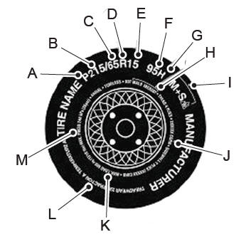
    P215/65R15 95H is an example of a tire size, load index and speed rating. The definitions of these items are listed below. (Note that the tire size, load index and speed rating for your vehicle may be different from this example.)

    P: Indicates a tire, designated by the Tire and Rim Association, that may be used for service on cars, sport utility vehicles, minivans and light trucks. Note: If your tire size does not begin with a letter this may mean it is designated by either the European Tire and Rim Technical Organization or the Japan Tire Manufacturing Association. 215: Indicates the nominal width of the tire in millimeters from sidewall edge to sidewall edge. In general, the larger the number, the wider the tire. 65: Indicates the aspect ratio which gives the tire's ratio of height to width. R: Indicates a radial type tire. 15: Indicates the wheel or rim diameter in inches. If you change your wheel size, you will have to purchase new tires to match the new wheel diameter. 95: Indicates the tire's load index. It is an index that relates to how much weight a tire can carry. You may find this information in your owner’s manual. If not, contact a local tire dealer.

    read more

    Copyright © 2024 www.licorsair.com