Lincoln Corsair: Automatic Transmission - Automatic Transmission – HF45 / Description and Operation - Transmission Description - System Operation and Component Description
System Diagram
E357528 *.sttxt { visibility: hidden; } *.stcallout { visibility: visible; } 1 ABS 2 BECM 3 DC/DC 4 GWM 5 PCM 6 ISC 7 Transmission 8 Motor/Generator Speed Sensors 9 Motor/Generator Coil Temp Sensors 10 TFT Sensor 11 Park Lock Actuator 12 Field Coils| Item | Description |
|---|---|
| 1 | ABS |
| 2 | BECM |
| 3 | DCDC |
| 4 | GWM |
| 5 | PCM |
| 6 | ISC (inverter system controller) |
| 7 | Transmission |
| 8 | Motor/Generator Speed Sensors |
| 9 | Motor/Generator Coil Temp Sensors |
| 10 | TFT Sensor |
| 11 | Park Lock Actuator |
| 12 | Field Coils |
Network Message Chart
| Broadcast Message | Originating Module | Message Purpose |
|---|---|---|
| ABS fault | ABS module | Supplies ABS system fault status. |
| Battery available status | BECM | Supplies HV system charge status. |
| Battery charge limit | BECM | How much charge the high voltage battery can accept. |
| Battery power charge/discharge | BECM | How much power the high voltage battery can provide. |
| Battery state of charge limit | BECM | Hazard lamp/malfunction indicator lamp illumination request. |
| Battery temperature (HV) | BECM | Determines the battery temperature for the actual state of charge. |
| Brake pedal movement | ABS module | Supplies brake status information for regenerative braking. |
| Engine RPM | PCM | Calculates engine torque. |
| PHEV / FHEV engine data | PCM | Calculates engine torque. |
| Regenerative braking mode | ABS module | Indicates when the brakes are applied to switch to regenerative braking mode. |
System Operation
Component Description
Sensors and Actuators
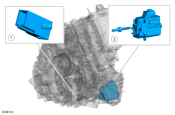
| Item | Description |
|---|---|
| 1 | TFT sensor |
| 2 | Park lock actuator |
The TFT sensor is a thermistor located on the internal transmission harness. It sends a voltage signal to the ISC (inverter system controller). The voltage signal varies with TFT . The TFT sensor can not be serviced in vehicle, the transmission must be removed and disassembled.
The park lock actuator is an internally mounted actuator. The park lock actuator engages the park pawl with the park gear when commanded by the ISC. The park lock actuator cannot be serviced in vehicle, the transmission must be removed and disassembled. The PCM uses the park lock actuator signal for range selection, torque calculation and reverse lamp operation.
Park
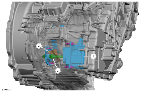
| Item | Description |
|---|---|
| 1 | Park lock actuator |
| 2 | Park pawl |
| 3 | Park rod |
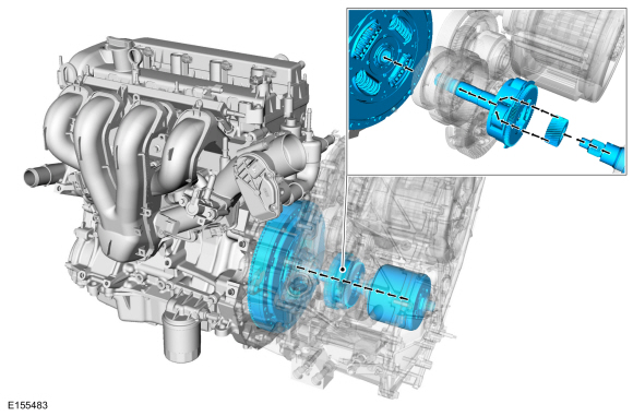
Power flow
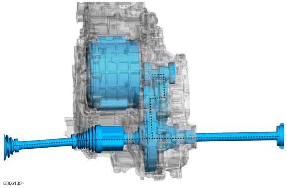
In electric mode, torque flows from the electric motor to the transfer shaft and to the final drive ring gear. When the engine is off, the planetary carrier is held and the planetary ring gear is driven by the transfer shaft. This action causes the sun gear and the generator/starter to rotate. Under certain conditions, the SOBDMC will command the generator/starter to produce electricity for the electric motor and to charge the batteries.
Engine Starting Power flow
To start the engine, the final drive works as a holding element to the ring gear in the planetary assembly. The generator/starter turns the sun gear to start the engine.
Engine Charging Power flow
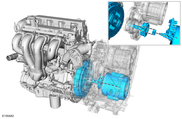
To charge the batteries, the final drive works as a holding element to the ring gear in the planetary assembly. The engine turns the carrier. This actions allows the generator/starter to produce current to charge the batteries and power the electric motor.
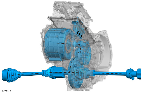
Regenerative Braking
When additional torque is needed to propel the vehicle, the generator/starter works as a holding element to the planetary sun gear. The flow of torque from the transfer shaft to the planetary ring gear is reversed and torque from the engine combines with the electric motor torque at the transfer shaft.

 Description and Operation - Pump Assembly - Plug-In Hybrid Electric Vehicle (PHEV)
Transmission Fluid Pump
Item
Part Number
Description
1
7A1037A103
Pump assembly
2
7P0867P086
Transmission fluid auxiliary pump
The
transmission fluid pump is an internal pump bolted to the transmission
case...
Other information:
Lincoln Corsair 2020-2024 Service Manual: Description and Operation - Glass, Frames and Mechanisms - System Operation and Component Description
System Operation System Diagram - Power Windows Driver Side Power Windows Item Description 1 LIN 2 Driver Side Front Window Motor 3 Driver Side Rear Window Control Switch 4 Driver Window Control Switch 5 DDM 6 Driver Side Rear Window Motor Passenger Side Power Windows Item Description 1 Passenger Fr..
Lincoln Corsair 2020-2024 Service Manual: Description and Operation - Glass, Frames and Mechanisms - Overview
Overview Power Windows The power windows operate only when the delayed accessory feature is active. The delayed accessory feature is active whenever the ignition is ON, or up to 10 minutes after the ignition is changed from ON to OFF while the front driver and passenger doors remain closed. Power Window Operation Standard power window features include one-touch up and one-touch dow..
Categories
- Manuals Home
- 1st Generation Lincoln Corsair Owners Manual
- 1st Generation Lincoln Corsair Service Manual
- Fuel Quality - Gasoline
- Remote Start Settings
- Refueling - Gasoline
- New on site
- Most important about car
Second Stage: Checking Tire Pressure
WARNING: If the tire does not inflate to the recommended tire pressure within 15 minutes, stop and call roadside assistance.
WARNING: The power plug may get hot after use and should be handled carefully when unplugging.
Check the air pressure of your tires as follows: