Lincoln Corsair: Power Steering / Removal and Installation - Steering Gear Boot
Lincoln Corsair 2020-2026 Service Manual / Chassis / Steering System / Power Steering / Removal and Installation - Steering Gear Boot
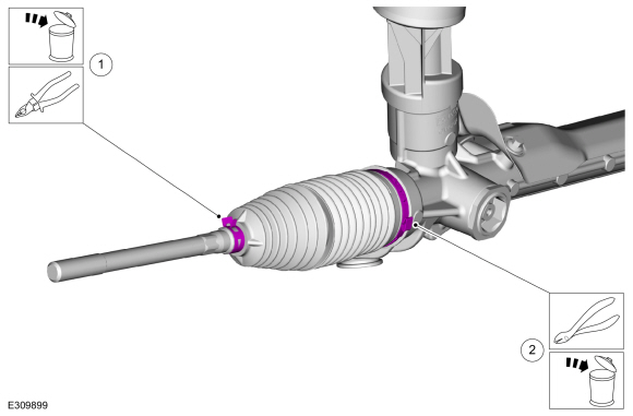
Special Tool(s) / General Equipment
| Boot Clamp Pliers |
Materials
| Name | Specification |
|---|---|
| Motorcraft® Premium Long-Life Grease XG-1-E1 |
ESA-M1C75-B |
Removal
NOTE: Left hand (LH) side shown, right (RH hand side ) similar.
-
Remove the tie rod end.
Refer to: Tie Rod End (211-02 Power Steering, Removal and Installation).
-
NOTE: Count and record the number of turns required to remove the tie rod end jam nut for reference during installation.
Remove the tie rod end jam nut.
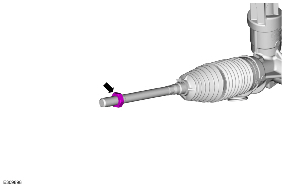 |
-
-
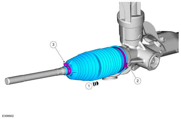
Remove and discard the outer steering gear boot clamp.
-
Remove and discard the inner steering gear boot clamp.
-
Remove and discard the outer steering gear boot clamp.
 |
-
Remove the steering gear boot.
 |
Installation
-
Apply the specified grease to the steering
gear-to-bellows boot mating surface and bellows boot groove on the inner
tie-rod.
Material: Motorcraft® Premium Long-Life Grease / XG-1-E1 (ESA-M1C75-B)
 |
-
NOTE: Make sure the steering gear bellows boot is positioned correctly over the steering gear housing bead and the groove in the inner tie rod.
-
Install the steering gear boot.
-
Install the new inner steering gear boot clamp.
Use the General Equipment: Boot Clamp Pliers
-
Install the new outer steering gear boot clamp.
-
Install the steering gear boot.
 |
-
Install the tie rod end.
Refer to: Tie Rod End (211-02 Power Steering, Removal and Installation).
 Removal and Installation - Steering Gear
Removal
Remove the front subframe.
Refer to: Front Subframe (502-00 Uni-Body, Subframe and Mounting System, Removal and Installation).
Remove and discard the steering gear retainers...
 Removal and Installation - Tie Rod
Removal
NOTE:
If servicing the RH (right-hand) tie rod, both bellows boots must be removed.
Remove the steering gear boot.
Refer to: Steering Gear Boot (211-02 Power Steering, Removal and Installation)...
Other information:
Lincoln Corsair 2020-2026 Service Manual: Removal and Installation - Tire Pressure Monitoring System (TPMS) Sensor
Removal WARNING: The Tire Pressure Monitoring System (TPMS) sensor battery may release hazardous chemicals if exposed to extreme mechanical damage. If these chemicals contact the skin or eyes, flush immediately with water for a minimum of 15 minutes and get prompt medical attention...
Lincoln Corsair 2020-2026 Service Manual: Removal and Installation - Air Cleaner
Removal NOTICE: The turbocharger compressor vanes can be damaged by even the smallest particles. When removing any turbocharger or engine air intake system component, ensure that no debris enters the system. Failure to do so may result in damage to the turbocharger...
Categories
- Manuals Home
- 1st Generation Lincoln Corsair Owners Manual
- 1st Generation Lincoln Corsair Service Manual
- Head Up Display
- Normal Scheduled Maintenance
- Automatic Transmission - 8-Speed Automatic Transmission – 8F35/8F40
- New on site
- Most important about car
360 Degree Camera Cameras
Locating the Rear View Camera

The rear view camera is on the tailgate.
Locating the Front View Camera
Copyright © 2026 www.licorsair.com