Lincoln Corsair: Steering Wheel and Column Electrical Components / Removal and Installation - Ignition Switch - Vehicles With: Push Button Start
Special Tool(s) /
General Equipment
Removal
NOTE:
Removal steps in this procedure may contain installation details.
-
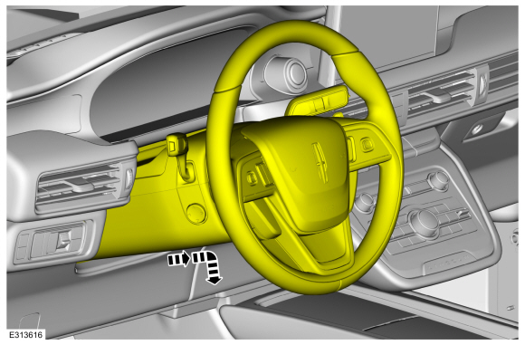
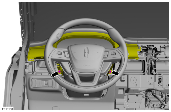
Fully extend and lower the steering column.
-
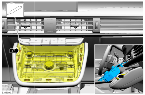
Remove the information and entertainment display unit.
Refer to: Center Display Screen (415-00 Information and Entertainment System - General Information, Removal and Installation).
-
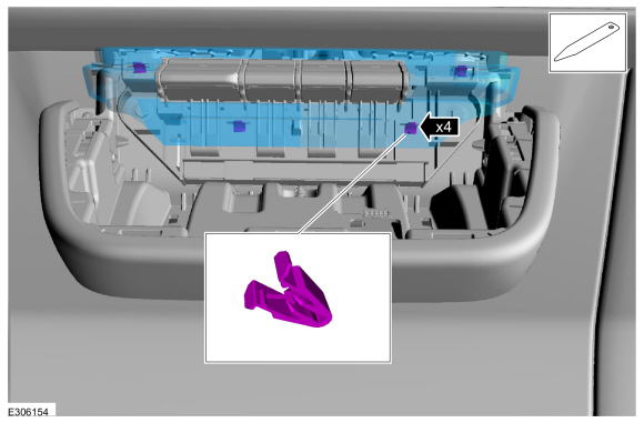
Release the clips, disconnect the electrical connector and remove the FCIMB and trim plate as an assembly.
Use the General Equipment: Interior Trim Remover
-
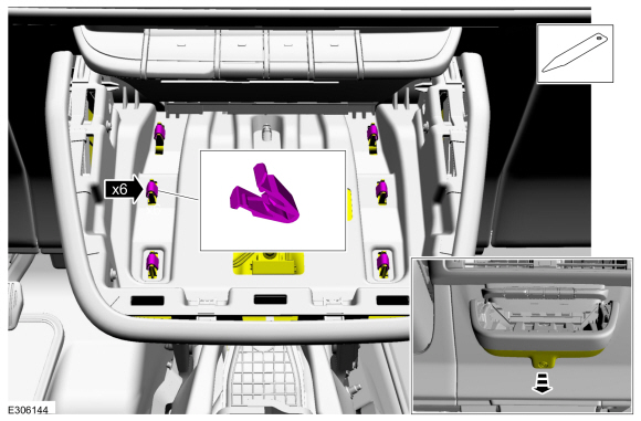
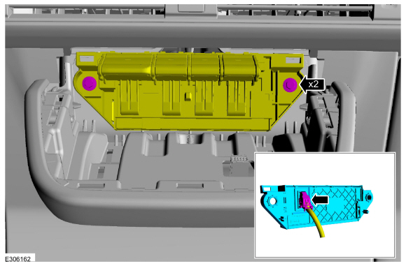
Release the clips and position the control panel lower trim plate down.
Use the General Equipment: Interior Trim Remover
-
Disconnect the electrical connector and remove the control panel lower trim plate.
-
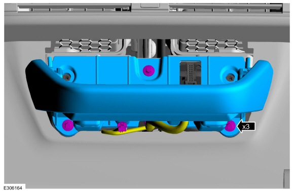
Release the clips and remove the transmission control switch trim plate.
-
Remove the retainers, disconnect the electrical connector and remove the transmission control switch.
-
Remove the retainers and the control panel support.
Torque:
44 lb.in (5 Nm)
-
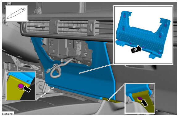
Release the clips and remove the center lower instrument panel trim panel.
Use the General Equipment: Interior Trim Remover
-
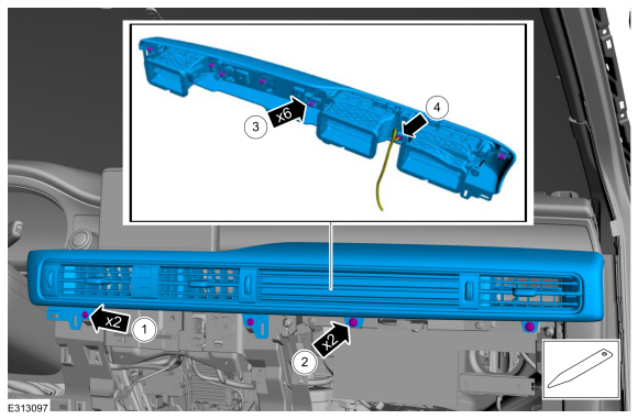
Remove the center registers.
-
Remove the retainers.
Torque:
22 lb.in (2.5 Nm)
-
Release the clips and position the center registers forward.
-
Disconnect the electrical connector.
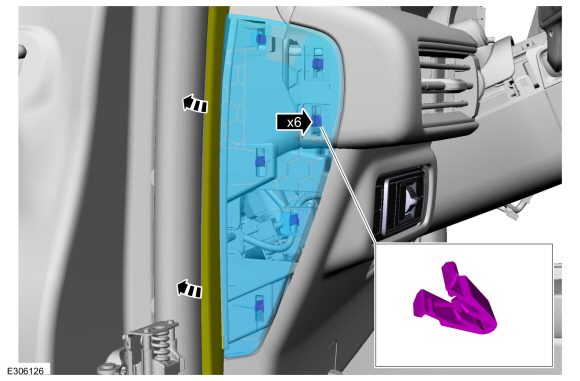
-
Position the front door weatherstrip aside, release that
clips and remove the LH (left-hand) instrument panel side finish panel.
Use the General Equipment: Interior Trim Remover
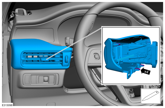
-
Release the clips and remove the finish panel.
Use the General Equipment: Interior Trim Remover
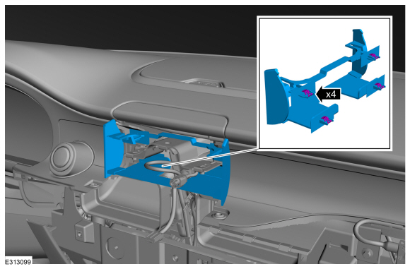
-
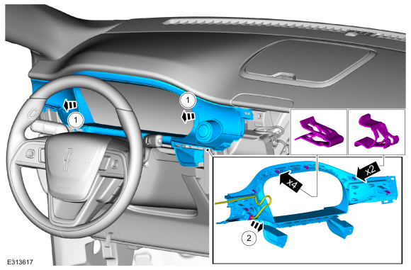
Release the clips and remove the instrument display bezel.
-
Remove the instrument cluster bezel retainers.
Torque:
33 lb.in (3.7 Nm)
-
Remove the instrument cluster bezel.
-
Release the clips, remove the instrument cluster bezel.
Use the General Equipment: Interior Trim Remover
-
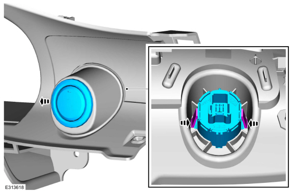
Disconnect the ignition switch electrical connector.
-
Release the tabs and push the start/stop switch out of the instrument panel finish panel.
Installation
-
To install, reverse the removal procedure.
Diagnostic Trouble Code (DTC) Chart
Diagnostics in this manual assume a certain skill level and knowledge of Ford-specific diagnostic practices. REFER to: Diagnostic Methods (100-00 General Information, Description and Operation)...
Removal
NOTE:
Removal steps in this procedure may contain installation details.
NOTE:
This step is only necessary when installing a new component...
Other information:
Switching Intelligent Mode On and Off
WARNING: You are responsible for
controlling your vehicle at all times. The
system is designed to be an aid and does
not relieve you of your responsibility to
drive with due care and attention. Failure
to follow this instruction could result in the
loss of control of your vehicle, personal
injury or death...
WARNING: Do not attach two child
safety restraints to the same anchor. In a
crash, one anchor may not be strong
enough to hold two child safety restraint
attachments and may break, causing
serious injury or death.
WARNING: Depending on where you
secure a child restraint, and depending on
the child restraint design, you may block
access to certain seatbelt buckle
assemblies and LATCH lower..

 Diagnosis and Testing - Steering Wheel and Column Electrical Components
 Removal and Installation - Steering Column Control Module (SCCM)