Lincoln Corsair: Front Drive Halfshafts / Removal and Installation - Front Halfshaft LH
Special Tool(s) / General Equipment
 |
204-161
(T97P-1175-A)
Installer, Halfshaft TKIT-1997-LM2 TKIT-1997-F/FM2 TKIT-1997-FLM2 |
 |
205-D070
(D93P-1175-B)
Remover, Front Wheel Hub |
| Tie Rod End Remover | |
Removal
-
Remove the wheel and tire.
Refer to: Wheel and Tire (204-04A Wheels and Tires, Removal and Installation).
-
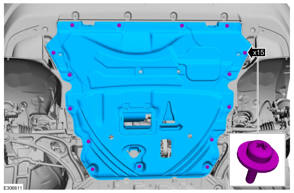
Remove the retainers and the underbody shield.
 |
-
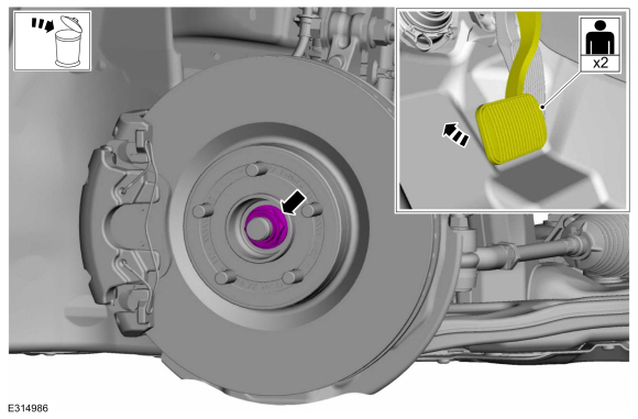
Remove and discard the wheel hub nut.
 |
-
-
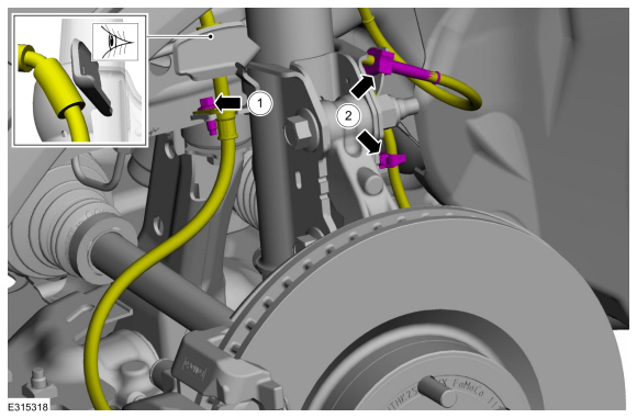
Remove the bolt and position aside the brake hose.
-
Unclip the 2 wire retainers and position aside the wheel speed sensor wiring harness.
-
Remove the bolt and position aside the brake hose.
 |
-
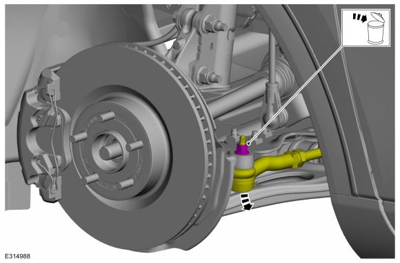
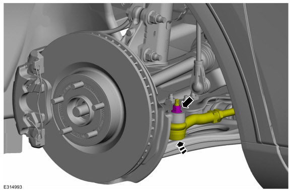
NOTICE: Do not use a hammer to separate the tie rod end from the wheel knuckle or damage to the wheel knuckle may result.
NOTICE: Use care when installing the tie rod separator or damage to the tie rod end boot may occur.
NOTE: Use the hex-holding feature to prevent turning of the stud while removing the tie rod end nut.
Remove and discard the tie rod end nut and separate the tie rod end from the wheel knuckle. Remove the halfshaft.
Use the General Equipment: Tie Rod End Remover
 |
-
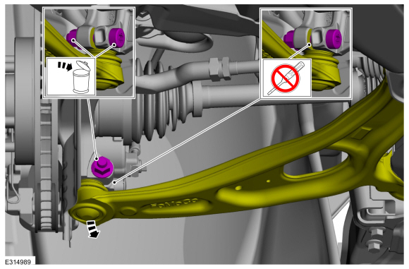
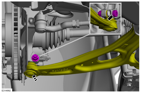
NOTICE: Do not use a prying device to open the slot in the knuckle to separate the lower ball joint from the knuckle assembly. Damage to the knuckle assembly may occur.
NOTICE: Do not use a prying device or separator fork between the ball joint and the wheel knuckle. Damage to the ball joint or ball joint seal may result. Only use the pry bar by inserting it into the lower arm body opening.
NOTICE: Use care when releasing the lower arm and wheel knuckle into the resting position or damage to the ball joint seal may occur.
NOTICE: Do not use power tools to remove or install the lower arm outboard nut. Damage to the ball joint or ball joint seal may occur.
NOTE: Use the TORX PLUS® holding feature to prevent the ball stud from turning while removing or installing the lower arm outboard nut. Torx® and TORX PLUS® is a reg. tm of Acument Intellectual Properties, LLC.
Remove and discard the ball joint pinch bolt and nut and separate the lower arm from the wheel knuckle.
 |
-
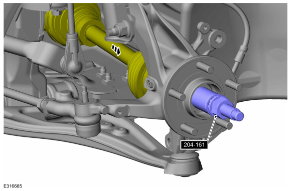
NOTICE: Do not bend the inner joint more than 18 degrees and the outer joint more than 45 degrees. Damage to the shaft will occur.
Using the special tool, press the halfshaft from the wheel bearing and hub. Support the halfshaft in a level position.
Use Special Service Tool: 205-D070 (D93P-1175-B) Remover, Front Wheel Hub.
 |
-
NOTE: Do not pull on the halfshaft. Pull or pry on the inner CV housing only or damage may occur.
Remove the halfshaft.
 |
-
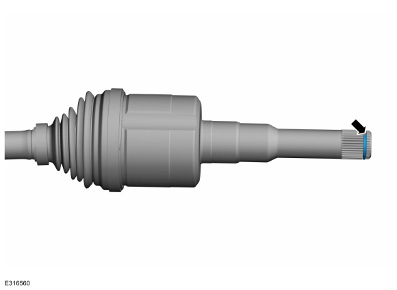
Remove and discard the halfshaft retaining circlip.
 |
Installation
-
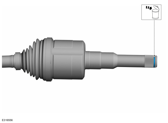
Clean and inspect the outer CV housing.
 |
-
Clean and inspect the inner CV housing.
 |
-
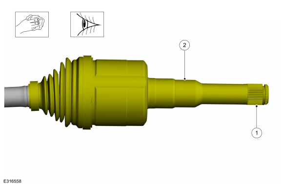
NOTE: Make sure new component is installed.
Install the new inner halfshaft retaining circlip.
 |
-
Replace the halfshaft seal.
Refer to: Halfshaft Seal LH (307-01A Automatic Transmission - 8-Speed Automatic Transmission – 8F35/8F40, Removal and Installation).
Refer to: Halfshaft Seal LH (307-01A Automatic Transmission - 8-Speed Automatic Transmission – 8F35/8F40, Removal and Installation).
Refer to: Halfshaft Seal LH (307-01A Automatic Transmission - 8-Speed Automatic Transmission – 8F35/8F40, Removal and Installation).
-
NOTE: Insert shaft until circlip is fully seated. When checking if circlip is seated do not pull on CV joints or damage can result.
NOTE: Pull on the inner CV joint to ensure the halfshaft circlip is seated properly.
Insert the halfshaft until the halfshaft retaining clip is fully seated.
 |
-
Pull the halfshaft into the front wheel bearing and wheel hub.
Use Special Service Tool: 204-161 (T97P-1175-A) Installer, Halfshaft.
 |
-
NOTICE: Do not use power tools to remove or install the lower arm outboard nut. Damage to the ball joint or ball joint seal may occur.
NOTE: Use the TORX PLUS® holding feature to prevent the ball stud from turning while removing or installing the lower arm outboard nut. Torx® and TORX PLUS® is a reg. tm of Acument Intellectual Properties, LLC.
Position the ball joint into the wheel knuckle and install the new ball joint pinch bolt and nut.
Torque: 81 lb.ft (110 Nm)
 |
-
NOTICE: Use care when installing the tie rod separator or damage to the tie rod end boot may occur.
NOTE: Use the hex-holding feature to prevent turning of the stud while installing the tie rod end nut.
Attach the tie rod end to the wheel knuckle and install the new tie rod end nut.
Torque: 35 lb.ft (48 Nm)
 |
-
-
Position the brake hose and install the bolt.
Torque: 97 lb.in (11 Nm)
-
Position the wheel speed sensor wiring harness and clip the 2 wire retainers.
-
Position the brake hose and install the bolt.
|
-
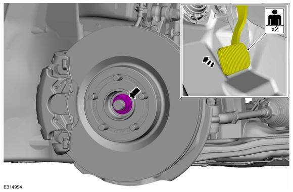
NOTICE: Do not tighten the front wheel hub nut with the vehicle on the ground. The nut must be tightened to specification before the vehicle is lowered onto the wheels. Wheel bearing damage will occur if the wheel bearing is loaded with the weight of the vehicle applied.
NOTICE: Install and tighten the new wheel hub nut to specification in a continuous rotation. Always install a new wheel hub nut after loosening or when not tightened to specification in a continuous rotation or damage to the components may occur.
NOTE: Apply the brake to keep the halfshaft from rotating.
While an assistant applies the brake, install the new wheel hub nut.
Torque:
Stage 1: 74 lb.ft (100 Nm)
Stage 2: 60°
 |
-
Check the transmission fluid level.
Refer to: Transmission Fluid Level Check (307-01A Automatic Transmission - 8-Speed Automatic Transmission – 8F35/8F40, General Procedures).
Refer to: Transmission Fluid Level Check (307-01A Automatic Transmission - 8-Speed Automatic Transmission – 8F35/8F40, General Procedures).
Refer to: Transmission Fluid Level Check (307-01A Automatic Transmission - 8-Speed Automatic Transmission – 8F35/8F40, General Procedures).
-
Install the underbody shield and tighten the retainers.
Torque: 13 lb.in (1.5 Nm)
|
-
Install the wheel and tire.
Refer to: Wheel and Tire (204-04A Wheels and Tires, Removal and Installation).
 Diagnosis and Testing - Front Drive Halfshafts
Preliminary Inspection
Visually inspect the CV joints, housing, boots, and clamps for obvious signs of mechanical damage.
If an obvious cause for an observed or reported concern is
found, correct the cause (if possible) before proceeding to the next
step
If the cause is not visually evident, verify the symptom and REFER to Symptom Chart: NVH...
 Removal and Installation - Front Halfshaft RH - 2.0L EcoBoost (177kW/240PS) – MI4, FWD
Special Tool(s) /
General Equipment
204-161
(T97P-1175-A)
Installer, HalfshaftTKIT-1997-LM2TKIT-1997-F/FM2TKIT-1997-FLM2
205-D070
(D93P-1175-B)
Remover, Front Wheel Hub
Tie Rod End Remover
Removal
Remove the wheel and tire...
Other information:
Lincoln Corsair 2020-2026 Service Manual: Removal and Installation - Front Impact Severity Sensor
Removal WARNING: The following procedure prescribes critical repair steps required for correct restraint system operation during a crash. Follow all notes and steps carefully. Failure to follow step instructions may result in incorrect operation of the restraint system and increases the risk of serious personal injury or death in a crash...
Lincoln Corsair 2020-2026 Owners Manual: Plug-In Hybrid Vehicle Operation
Regularly plug in your vehicle to get optimal electric-only range capability from the high voltage battery. Charging your vehicle adds electrical energy. This energy propels the vehicle. Estimated electric-only driving range shows in blue next to the gasoline range on the information display...
Categories
- Manuals Home
- 1st Generation Lincoln Corsair Owners Manual
- 1st Generation Lincoln Corsair Service Manual
- Opening and Closing the Hood
- Auto-Start-Stop
- Programming the Garage Door Opener to Your Hand-Held Transmitter
- New on site
- Most important about car
Information on P Type Tires
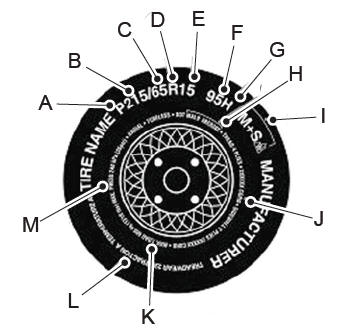
P215/65R15 95H is an example of a tire size, load index and speed rating. The definitions of these items are listed below. (Note that the tire size, load index and speed rating for your vehicle may be different from this example.)
P: Indicates a tire, designated by the Tire and Rim Association, that may be used for service on cars, sport utility vehicles, minivans and light trucks. Note: If your tire size does not begin with a letter this may mean it is designated by either the European Tire and Rim Technical Organization or the Japan Tire Manufacturing Association. 215: Indicates the nominal width of the tire in millimeters from sidewall edge to sidewall edge. In general, the larger the number, the wider the tire. 65: Indicates the aspect ratio which gives the tire's ratio of height to width. R: Indicates a radial type tire. 15: Indicates the wheel or rim diameter in inches. If you change your wheel size, you will have to purchase new tires to match the new wheel diameter. 95: Indicates the tire's load index. It is an index that relates to how much weight a tire can carry. You may find this information in your owner’s manual. If not, contact a local tire dealer.