Lincoln Corsair: Wheels and Tires / General Procedures - Wheel to Tire Runout Minimization
Check
NOTICE: Non-Hunter brand balancers will not include the Ford-approved procedure for match-mounting in their software.
NOTICE: Other balancing procedures that exist on non-Hunter brand equipment are not Ford approved and should not be used.
NOTE: Road Force® values in illustrations are shown in pounds.
NOTE: Match mounting is a technique used to reduce radial runout or road force on wheel and tire assemblies. Excessive runout is a source of ride quality complaints and match mounting can be used to minimize the runout. Match mounting can be accomplished by changing the position of the tire on the wheel.
NOTE: Diagnosis of tire/wheel vibration should not be performed on tires with less than 200 mi (322 km).
NOTE: Possible short-term tire flat-spotting should be eliminated by driving the vehicle 20 or more miles just prior to taking Road Force® measurements.
-
To ensure a tire/wheel vibration is the cause of the customer concern.
Refer to: Noise, Vibration and Harshness (NVH) (100-04) .
-
To eliminate possible short-term tire flat-spotting
drive the vehicle 20 or more miles just prior to taking Road Force®
measurements.
-
Before a warranty claim can be made on tire(s) with
out-of-spec Road Force® or runout measurements, the Wheel to Tire Runout
Minimization procedure (sometimes referred to as “match-mounting”,
“re-indexing”, or “Road Force® balancing”) found below must be
performed. This procedure is designed to optimize a tire’s mounting
position on a wheel in order to reduce the total Road Force® or runout
of the assembly. The procedure can be performed using either Road Force®
measurements (the preferred method). Road Force® measurements are taken
using a Road Force® balancer machine. The manner in which the Wheel to
Tire Runout Minimization procedure is carried out will sometimes vary
depending on the model of equipment used. Use the information below to
help identify the equipment type used at your dealership, then follow
the instructions outlined for that equipment. If your equipment
software does not include the Ford-approved procedure, it may be
available through hardware/software upgrades. Contact your local Hunter
representative for more details.
-
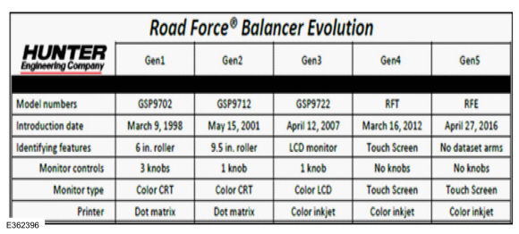
Determine the equipment type used at dealership or
tire/wheel balancing. Refer Hunter Equipment Model Identification for
identifying equipment type.
 |
-
GEN I and GEN II
-
Gen I and Gen II balancer models do not include software that follows the Ford Workshop Manual methodology.
-
The match-mounting procedures in the software of
these models should not be used. Instead, only the Wheel to Tire Runout
Minimization Procedure found above, should be used.
-
Use these machines only to gather the necessary Road
Force® measurements. Do not follow the prompts that appear for
match-mounting.
-
Gen I and Gen II balancer models do not include software that follows the Ford Workshop Manual methodology.
 |
-
GEN III
-
Gen III model balancer may include a procedure for
“Match Without Rim Runout” on the balancer display. If this procedure
is not included, then the Wheel to Tire Runout Minimization Procedure
above should be followed.
-
Another balancing procedure likely exists on Gen
III equipment. Do not use that procedure, only the Hunter “Match
Without Rim Runout” and Ford WSM Wheel to Tire Runout Minimization
Procedure are approved for use on Ford tire/wheel assemblies.
-
The “Match Without Rim Runout” procedure should
become the machine default setting after the first usage. If it does
not become the default than you will need to select it each time.
-
Gen III model balancer may include a procedure for
“Match Without Rim Runout” on the balancer display. If this procedure
is not included, then the Wheel to Tire Runout Minimization Procedure
above should be followed.
 |
-
GEN IV and GEN V
-
Gen IV and GEN V balancer models include a procedure
for “180 Matching” on the balancer display. This is the only Hunter
procedure that matches the Wheel to Tire Runout Minimization Procedure.
-
A second balancing procedure (it may be the default)
likely exists on your equipment. Do not use that procedure. If you
cannot default your machine to the 180 Matching Procedure, then it will
need to be selected each time.
-
The 180 Matching Procedure can be launched by
selecting the following buttons: Road Force® - Procedures - 180
Matching.
-
Gen IV and GEN V balancer models include a procedure
for “180 Matching” on the balancer display. This is the only Hunter
procedure that matches the Wheel to Tire Runout Minimization Procedure.
 |
-
The 180 Matching Procedure can be launched by selecting the following buttons:
-
Road Force®
-
Procedures
-
180 Matching
-
Road Force®
 |
-
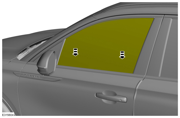
NOTE: Position the wheel and tire assembly on a tire machine and put a reference mark on the tire sidewall at the valve stem position.
-
Valve stem
-
Reference mark
-
Valve stem
 |
-
NOTICE: For vehicles equipped with a TPMS , the sensor may be damaged by incorrect tire mounting or dismounting. Dismount the tire from the wheel as instructed in the procedure. Failure to follow these instructions may result in TPMS component damage.
NOTE: Always make sure that the final high spot and measurement values are permanently marked on the inward sidewall of the tire for reference during future wheel and tire service.
Using a suitable tire machine, separate the tire beads from the wheel.
-
Lubricate the tire beads using a suitable fast drying,
corrosion inhibiting tire bead lubricant. Position the tire 180 degrees
(half-way around) on the rim so the valve stem reference mark is now
opposite the valve stem.
-
Re-inflate the wheel and tire assembly to the specified
air pressure and measure the assembly again using a suitable dial
indicator or Hunter Road Force® 9700 Series Wheel Balancer. Mark the
second high spot on the tire.
-
If the runout or Road Force is reduced to within
specifications, the concern has been resolved. Balance the assembly and
install on the vehicle using the Wheel-to-Hub Optimization procedure.
-
If the second runout or Road Force® measurement is still
not within specification and both high spots are close to each other
(within 101.6 mm [4 in]), the root cause is probably the tire (the high
spot followed the tire).
-
-
First high spot on the tire
-
Second high spot on the tire
-
First high spot on the tire
 |
-
To be SURE that the tire is causing the high runout, it
is necessary to have 2 runout or Road Force® measurements that are not
within specification and the high spots must be in approximately the
same location on the tire's sidewall. If the tire is the cause, install a
new tire, balance the assembly and install on the vehicle using the
Wheel-to-Hub Optimization procedure. If the second high spot is not
within 101.6 mm (4 in) of the first high spot, proceed to the next step.
-
If the second high spot is still above specification and
is within 101.6 mm (4 in) of being opposite the first high spot on the
wheel, the root cause is probably the wheel (the high spot followed the
wheel). Dismount the tire from the wheel, mount the wheel on a balancer
and check the wheel runout. If the wheel runout exceeds 1.14 mm (0.0449
in), install a new wheel, balance the assembly and install on the
vehicle using the Wheel-to-Hub Optimization procedure.
Refer to: Wheel to Hub Runout Minimization (204-04A Wheels and Tires, General Procedures).
-
-
First high spot on the tire
-
Second high spot on the tire
-
First high spot on the tire
 |
-
NOTE: If the second high spot did not follow the wheel or the tire and the runout is still not within specification, improvements may be made by rotating the tire 90 degrees (one-fourth turn).
Draw an arrow on the tire sidewall from the second high spot towards the first high spot (in the shortest direction).
-
-
First high spot on the tire
-
Second high spot on the tire
-
First high spot on the tire
 |
-
Separate the tire beads from the wheel and rotate the
tire 90 degrees (one-fourth turn) in the direction of the arrow.
 General Procedures - Wheel to Hub Runout Minimization
Check
NOTE:
Wheel-to-hub optimization is important. Clearance between
the wheel and hub can be used to offset or neutralize the Road Force® or
run-out of the wheel and tire assembly...
 Removal and Installation - Wheel and Tire
Materials
Name
Specification
Motorcraft® High Temperature Nickel Anti-Seize LubricantXL-2
-
Removal
With the vehicle in NEUTRAL, position it on a hoist...
Other information:
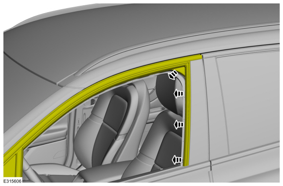
Lincoln Corsair 2020-2026 Service Manual: Specifications
Specifications Item Specification Front sliding glass panel to front trim panel flushness 0.066 ± 0.106 in (1.7 ± 2.7 mm) Front sliding glass panel to front trim panel distance 0...
Lincoln Corsair 2020-2026 Owners Manual: Ambient Lighting (IF EQUIPPED)
Use the touchscreen to select the following: Select the settings option on the feature bar. Select ambient lighting. Switching Ambient Lighting On Touch a color once. Changing the Color Touch any color once. Adjusting the Brightness Drag the selected color up or down...
Categories
- Manuals Home
- 1st Generation Lincoln Corsair Owners Manual
- 1st Generation Lincoln Corsair Service Manual
- General Procedures - Brake Service Mode Activation and Deactivation
- Normal Scheduled Maintenance
- Exterior Mirrors
- New on site
- Most important about car
Information on P Type Tires
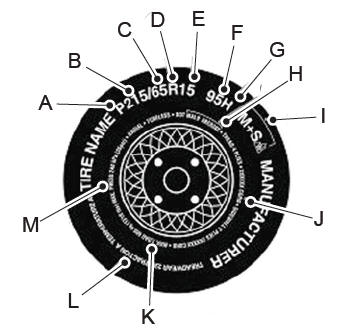
P215/65R15 95H is an example of a tire size, load index and speed rating. The definitions of these items are listed below. (Note that the tire size, load index and speed rating for your vehicle may be different from this example.)
P: Indicates a tire, designated by the Tire and Rim Association, that may be used for service on cars, sport utility vehicles, minivans and light trucks. Note: If your tire size does not begin with a letter this may mean it is designated by either the European Tire and Rim Technical Organization or the Japan Tire Manufacturing Association. 215: Indicates the nominal width of the tire in millimeters from sidewall edge to sidewall edge. In general, the larger the number, the wider the tire. 65: Indicates the aspect ratio which gives the tire's ratio of height to width. R: Indicates a radial type tire. 15: Indicates the wheel or rim diameter in inches. If you change your wheel size, you will have to purchase new tires to match the new wheel diameter. 95: Indicates the tire's load index. It is an index that relates to how much weight a tire can carry. You may find this information in your owner’s manual. If not, contact a local tire dealer.