Lincoln Corsair: Roof Opening Panel / Diagnosis and Testing - Roof Opening Panel
Diagnostic Trouble Code (DTC) Chart
Diagnostics in this manual assume a certain skill level and knowledge of Ford-specific diagnostic practices.
REFER to: Diagnostic Methods (100-00 General Information, Description and Operation).
| Module | DTC | Description | Action |
|---|---|---|---|
| BCM | B12F4:12 | Vehicle Speed Output: Circuit Short To Battery | GO to Pinpoint Test A |
| BCM | B12F4:14 | Vehicle Speed Output: Circuit Short To Ground Or Open | GO to Pinpoint Test A |
Global Customer Symptom Code (GCSC) Chart
Diagnostics in this manual assume a certain skill level and knowledge of Ford-specific diagnostic practices.
REFER to: Diagnostic Methods (100-00 General Information, Description and Operation).
| Symptom | Action |
|---|---|
| Fit/Finish/Body > Body Panels > Roof Opening Panel (Non-Glass) > Difficult to Close | GO to Pinpoint Test A |
| Fit/Finish/Body > Body Panels > Roof Opening Panel (Non-Glass) > Difficult to Close | GO to Pinpoint Test F |
| Fit/Finish/Body > Body Panels > Roof Opening Panel (Non-Glass) > Difficult to Open | GO to Pinpoint Test F |
| Fit/Finish/Body > Body Panels > Roof Opening Panel (Non-Glass) > Water Leak | GO to Pinpoint Test C |
| Fit/Finish/Body > Noise > Roof/Roof Opening > Always | GO to Pinpoint Test E |
Symptom Charts
Symptom Chart: Roof Opening Panel
Diagnostics in this manual assume a certain skill level and knowledge of Ford-specific diagnostic practices.G2085851
| Condition | Actions |
|---|---|
| The roof opening panel leaks |
|
| The roof opening panel does not open or close |
|
| The one-touch open feature is inoperative |
|
| The roof opening panel does not close with vehicle moving |
|
Symptom Chart: NVH
Diagnostics in this manual assume a certain skill level and knowledge of Ford-specific diagnostic practices.
REFER to: Diagnostic Methods (100-00 General Information, Description and Operation).
| Condition | Actions |
|---|---|
| The roof opening panel has excessive wind noise |
|
| The roof opening panel rattles |
|
| Roof opening panel is noisy during operation |
|
Symptom Chart: Shield
Diagnostics in this manual assume a certain skill level and knowledge of Ford-specific diagnostic practices.
REFER to: Diagnostic Methods (100-00 General Information, Description and Operation).
| Condition | Actions |
|---|---|
| The Shield Does Not Open or Close |
|
Pinpoint Tests
|
Refer to Wiring Diagrams Cell 101 for schematic and connector information. Normal Operation and Fault Conditions When the vehicle is in motion the BCM sends a PWM signal to the roof opening panel sliding glass motor which then will apply increased force while closing the roof opening panel sliding glass to reduce the possibility of bounce back. The roof opening panel motor must be initialized
when repairs are carried out on any part of the roof opening panel
system or when the roof opening panel motor, glass, assembly, or air
deflector has been removed or replaced for any reason. REFER to: Power
Roof Opening Panel Initialization (501-17 Roof Opening Panel, General
Procedures). DTC Fault Trigger Conditions
Possible Sources
|
||||||||||
| A1 CHECK THE VEHICLE SPEED OUTPUT CIRCUIT FOR A SHORT TO BATTERY | ||||||||||
Is any voltage present?
|
||||||||||
| A2 CHECK THE VEHICLE SPEED OUTPUT CIRCUIT FOR A SHORT TO GROUND | ||||||||||
Is the resistance greater than 10,000 Ohms?
|
||||||||||
| A3 CHECK THE VEHICLE SPEED OUTPUT CIRCUIT FOR AN OPEN | ||||||||||
Is the resistances less than 3 ohms?
|
||||||||||
| A4 CHECK THE ROOF OPENING PANEL JUMPER HARNESS | ||||||||||
Is the roof opening panel jumper harness OK?
|
||||||||||
| A5 CHECK FOR CORRECT ROOF OPENING PANEL MOTOR OPERATION | ||||||||||
Is the concern still present?
|
.jpg)
.jpg)
|
Normal Operation and Fault Conditions During normal operation the sunroof seals against the roof opening tightly and evenly preventing wind noise. Any failure to seal will cause wind noise. The roof opening panel motor must be initialized
when repairs are carried out on any part of the roof opening panel
system or when the roof opening panel motor, glass, assembly, or air
deflector has been removed or replaced for any reason. REFER to: Power
Roof Opening Panel Initialization (501-17 Roof Opening Panel, General
Procedures). Possible Sources
Visual Inspection and Pre-checks
|
||||
| B1 VERIFY ROOF OPENING PANEL NOISE | ||||
|
NOTE: It is normal to have some amount of wind noise when the roof opening panel is in the OPEN position. To determine if the wind noise is excessive, road test the vehicle at approximately 100 km/h (62 mph) with the roof opening panel closed, a single rear door window open and all remaining door windows closed while observing the level of wind noise. If the level of wind noise observed with the roof opening panel open (with all door windows closed) is greater than the wind noise observed with a single rear door window open, the wind noise is excessive.
Is the wind noise present only in the OPEN position?
|
||||
| B2 CHECK THE ROOF OPENING PANEL GLASS SEALS | ||||
|
NOTE: When the roof opening panel sliding glass is in the VENT position, make sure that the leading edge of the glass is in contact with the sliding glass primary seal.
Are the seals OK?
|
||||
| B3 CHECK THE AIR DEFLECTOR | ||||
Is the air deflector OK?
|
|
Normal Operation and Fault Conditions When the roof opening panel glass is completely closed, it is flush with the roof panel. The roof opening panel primary seal provides a seal against adverse weather conditions such as rain and wind, preventing them from entering the passenger compartment. A damaged, deformed or incorrectly installed seal is unable to seal the glass efficiently. Possible Sources
Visual Inspection and Pre-checks
|
||||
| C1 CHECK THE ROOF OPENING PANEL MOTOR INITIALIZATION | ||||
Is the concern still present?
|
||||
| C2 VERIFY THE LEAK IS NOT FROM THE WINDSHIELD | ||||
Is the leak coming from the windshield?
|
||||
| C3 VERIFY THE ROOF OPENING PANEL LEAK LOCATION | ||||
Is the leak coming from the roof opening panel fixed glass or antenna area of the roof opening panel?
|
||||
| C4 CHECK THE ROOF OPENING PANEL PRIMARY SEAL CONDITION | ||||
Is the roof opening panel primary seal in good condition and free from damage?
|
||||
| C5 CHECK THE ROOF OPENING PANEL FRAME URETHANE SEAL | ||||
Is the roof opening panel frame urethane seal OK?
|
||||
| C6 CHECK THE CONDITION OF THE ROOF OPENING PANEL TRACK ASSEMBLIES | ||||
Are the assemblies OK
|
|
Normal Operation and Fault Conditions When the roof opening panel glass is completely closed, it is flush with the roof panel. All components should be secured correctly. The roof opening panel system is made up of many components that require specific torque specifications and correct installation in order to avoid any NVH concerns. Over time, components may become loose or damaged, fasteners may become loose, sound insulating material may wear out and foreign material may collect in the roof opening panel frame. It is possible that one or more of these conditions may lead to a rattle concern in the roof opening panel system. Possible Sources
|
||||
| D1 CHECK THE ROOF OPENING PANEL GLASS OPERATION | ||||
Is the roof opening panel glass loose?
|
||||
| D2 CHECK THE ROOF OPENING PANEL TRACKS | ||||
Are the tracks OK?
|
||||
| D3 CHECK THE ROOF OPENING PANEL SHIELD | ||||
Is the shield installed correctly?
|
||||
| D4 CHECK THE ROOF OPENING PANEL | ||||
Is the roof opening panel assembly OK?
|
|
Normal Operation and Fault Conditions When the roof opening panel glass closes, it should do so quietly and smoothly. The roof opening panel system is made up of many components that require specific torque specifications and correct installation in order to avoid any NVH concerns. Over time, components may become loose or damaged, fasteners may become loose, sound insulating material may wear out and foreign material may collect in the roof opening panel frame. It is possible that one or more of these conditions may lead to a noise concern in the roof opening panel system. Possible Sources
|
||||
| E1 CHECK THE ROOF OPENING PANEL GLASS FOR OBSTRUCTIONS OR DAMAGE | ||||
Are there any obstructions and/or damage?
|
||||
| E2 CHECK THE ROOF OPENING PANEL GLASS OPERATION | ||||
Is the roof opening sliding glass loose?
|
||||
| E3 CHECK THE ROOF OPENING PANEL TRACKS | ||||
Are the tracks OK?
|
||||
| E4 CHECK THE ROOF OPENING PANEL SHIELD | ||||
Is the roof opening panel shield moving correctly?
|
||||
| E5 CHECK THE ROOF OPENING PANEL MOTORS | ||||
Is the roof opening panel glass motor OK?
|
|
Refer to Wiring Diagrams Cell 101 for schematic and connector information. Normal Operation and Fault Conditions The roof opening panel motor receives battery voltage at all times
from BCM fuse F37 (30A), and receives ignition voltage (accessory delay)
from BCM
fuse F6 (10A). The roof opening panel motor and switch are grounded at
G303. When the roof opening panel switch is pressed, a ground signal is
sent to the roof opening panel motor on the sunroof open circuit. When
the roof opening panel switch is pulled, a ground signal is sent to the
roof opening panel motor on the sunroof close circuit. When the roof
opening panel tilt switch is pressed, a ground signal is sent to the
roof opening panel motor on the tilt/vent switch circuit. The motor
responds to these signals dependant on the sliding glass panel and
shield positions. One touch operation is accomplished by pressing any of
the switches for less than 1 second. For more information on the
operation, REFER to: Roof Opening Panel - System Operation and Component
Description (501-17 Roof Opening Panel, Description and Operation). There is a communication circuit between the shield motor and the sunroof motor for back and fourth communication between the 2 motors only, and not for diagnostics. If the communication circuit between the sunroof motor and shield motor is open or shorted the sunroof motor will operate only to fully close the sliding glass, and the shield motor will not operate at all. Possible Sources
Visual Inspection and Pre-checks
|
|||||||||||||
| F1 CHECK THE POWER WINDOW OPERATION | |||||||||||||
Do the power windows operate properly?
|
|||||||||||||
| F2 CHECK THE SHIELD OPERATION | |||||||||||||
Does the shield operate as expected?
|
|||||||||||||
| F3 CHECK THE ROOF OPENING PANEL GLASS OPERATION | |||||||||||||
Does the glass operate as expected?
|
|||||||||||||
| F4 CHECK THE ROOF OPENING PANEL MOTOR CONTROL CIRCUITS FOR A SHORT TO VOLTAGE | |||||||||||||
Is any voltage present?
|
|||||||||||||
| F5 CHECK THE ROOF OPENING PANEL MOTOR CONTROL CIRCUITS FOR A SHORT TO GROUND | |||||||||||||
Are the resistances less than 10,000 ohms?
|
|||||||||||||
| F6 CHECK THE ROOF OPENING PANEL MOTOR CONTROL CIRCUITS FOR AN OPEN | |||||||||||||
Are the resistances less than 3 ohms?
|
|||||||||||||
| F7 CHECK THE ROOF OPENING PANEL MOTOR CONTROL CIRCUITS FOR A SHORT TOGETHER | |||||||||||||
Are the resistances greater than 10,000 ohms?
|
|||||||||||||
| F8 CHECK ROOF OPENING PANEL CONTROL SWITCH GROUND CIRCUIT | |||||||||||||
Is the resistance less than 3 ohms?
|
|||||||||||||
| F9 CHECK THE ROOF OPENING PANEL MODULE GROUND CIRCUIT | |||||||||||||
Is the resistance less than 3 ohms?
|
|||||||||||||
| F10 CHECK THE ROOF OPENING PANEL MODULE VOLTAGE CIRCUITS | |||||||||||||
Are the voltages greater than 11 volts?
|
|||||||||||||
| F11 CHECK THE ROOF OPENING PANEL JUMPER HARNESS | |||||||||||||
Is the roof opening panel jumper harness OK?
|
|||||||||||||
| F12 CHECK THE ROOF OPENING PANEL MOTOR/MODULES AND SWITCH FOR CORRECT OPERATION | |||||||||||||
Is the concern still present?
|
|
Refer to Wiring Diagrams Cell 101 for schematic and connector information. Normal Operation and Fault Conditions The shield motor receives battery voltage at all times from BCM fuse F37 (30A), and receives ignition voltage (accessory delay) from BCM fuse F6 (10A). The roof opening panel motor and switch is grounded through circuit G200. When the shield open switch is pressed, a signal is sent to the shield motor on sunshade open circuit which causes the shield to open. When the shield close switch is pressed, a signal is sent to the shield motor on the sunshade close circuit which causes the shield to close. If the K bus (communication) circuit between the sunroof motor and shield motor is open or shorted the sunroof motor will only fully close the sunroof one time, then not operate. Also, if the K bus circuit is open or shorted the shield motor will not operate but the roof opening panel close to the fully closed position 1 time. If the shield is not open at least to the front of the rear glass (comport stop), the glass will not open. Possible Sources
|
|||||||||||||
| G1 CHECK THE SHIELD CONTROL CIRCUITS FOR A SHORT TO VOLTAGE | |||||||||||||
Is any voltage present?
|
|||||||||||||
| G2 CHECK THE SHIELD CONTROL CIRCUITS FOR A SHORT TO SHORT TO GROUND | |||||||||||||
Are the resistances greater than 10,000 ohms?
|
|||||||||||||
| G3 CHECK THE SHIELD CONTROL CIRCUITS FOR AN OPEN | |||||||||||||
Are the resistances less than 3 ohms?
|
|||||||||||||
| G4 CHECK THE SHIELD CONTROL CIRCUITS FOR A SHORT TOGETHER | |||||||||||||
Are the resistances greater than 10,000 ohms?
|
|||||||||||||
| G5 CHECK THE ROOF OPENING PANEL JUMPER HARNESS | |||||||||||||
Is the roof opening panel jumper harness OK?
|
|||||||||||||
| G6 CHECK THE ROOF OPENING PANEL MOTOR/MODULES AND SWITCH FOR CORRECT OPERATION | |||||||||||||
Is the concern still present?
|
|
Refer to Wiring Diagrams Cell 101 for schematic and connector information. Normal Operation and Fault Conditions All of the roof opening panel switches are single
position switches that can achieve one touch operation in either
direction by pressing the switch for less than 1 second. For manual
operation, simply press and hold the switch until the roof opening panel
or shield is in the desired position and release the switch. When the
front roof opening panel is in the fully closed or between fully closed
and full vent position the vent switch operates in either manual or one
touch operation similar to the roof opening panel and shield switches.
If the shield is not open at lease to the front of the rear fixed glass
(comfort stop) when the vent or roof opening panel glass open switch is
pressed then the shield will first open to the comfort stop position
before the roof opening panel glass will move. The roof opening panel
glass and the shield will not move at the same time. One touch operation
of either the roof opening panel or the shield can be cancelled anytime
by pressing any roof opening panel switches during operation. When the
sunroof is open and the sunroof close switch is pressed for one touch
operation, a signal is sent to the sunroof motor through on the sunroof
close circuit causing the sunroof to perform a one-touch close operation
(closes to approximately 8 in. (200mm) from the closed position only).
The sunroof open one touch operation is the same as sunroof close,
except if the shield is closed when the sunroof motor is commanded to
perform a one-touch open operation the motors will communicate and the
shield motor will perform a one-touch open operation, then the sunroof
motor will perform the one-touch open operation requested. The shield
one touch operation is the same as the sunroof except if the sunroof is
open, the shield will only move to the comfort stop position. The
sunroof will not open as a result of a shield one touch close operation.
For more information on the operation. REFER to: Roof Opening Panel -
System Operation and Component Description (501-17 Roof Opening Panel,
Description and Operation). Possible Sources
|
||||
| H1 CHECK THE ROOF OPENING PANEL MOTORS FOR INITIALIZATION | ||||
Is the concern still present?
|
||||
| H2 CHECK THE ROOF OPENING PANEL MOTOR/MODULES AND SWITCH FOR CORRECT OPERATION | ||||
Is the concern still present?
|

 General Procedures - Power Roof Opening Panel Initialization
Initialization
WARNING:
Keep objects and body parts clear of the glass panel when
carrying out the initialization procedure. During the initialization
procedure, the glass panel closes with high force and cannot detect
objects in its path...
Other information:
Lincoln Corsair 2020-2026 Service Manual: Diagnosis and Testing - Suspension System
Symptom Chart: Suspension System Diagnostics in this manual assume a certain skill level and knowledge of Ford-specific diagnostic practices.REFER to: Diagnostic Methods (100-00 General Information, Description and Operation). Condition Actions Wander GO to Pinpoint Test A Front bottoming or riding low GO to Pinpoint T..
Lincoln Corsair 2020-2026 Owners Manual: Engine Oil Dipstick. Engine Oil Check. Oil Change Indicator Reset
Engine Oil Dipstick Minimum. Nominal. Maximum. Engine Oil Check WARNING: Do not work on a hot engine. To check the engine oil level consistently and accurately, do the following: Make sure the parking brake is on. Make sure the transmission is in park (P) or neutral (N). Run the engine until it reaches normal operating temperature. Make sure that your vehicle is on level ground..
Categories
- Manuals Home
- 1st Generation Lincoln Corsair Owners Manual
- 1st Generation Lincoln Corsair Service Manual
- Fuel Quality - Gasoline
- Exterior Mirrors
- Refueling - Gasoline
- New on site
- Most important about car
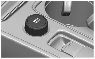
Selecting a Drive Mode. DRIVE MODES
Selecting a Drive Mode
Note: Drive mode changes may not be available when the ignition is off.