Lincoln Corsair Manuals

Lincoln Corsair: Wipers and Washers / Diagnosis and Testing - Wipers and Washers

Diagnostic Trouble Code (DTC) Chart

Diagnostics in this manual assume a certain skill level and knowledge of Ford-specific diagnostic practices.


Module DTC Description Action
BCM B130F:12 Run Accessory Control: Circuit Short To Battery GO to Pinpoint Test A
BCM B130F:14 Run Accessory Control: Circuit Short To Ground Or Open GO to Pinpoint Test A
BCM B13A4:11 Front Wiper Fast Mode Input: Circuit Short To Ground GO to Pinpoint Test D
SCCM B10AD:01 Rain Sensor: General Electrical Failure GO to Pinpoint Test F
SCCM B10AD:02 Rain Sensor: General Signal Failure GO to Pinpoint Test F
SCCM B10AD:08 Rain Sensor: Bus Signal/Message Failures GO to Pinpoint Test F
SCCM B10AD:49 Rain Sensor: Internal Electronic Failure GO to Pinpoint Test F
SCCM B10AD:49 Rain Sensor: Internal Electronic Failure GO to Pinpoint Test P
SCCM B10AD:55 Rain Sensor: Not Configured GO to Pinpoint Test O
SCCM B10AD:9A Rain Sensor: Component or System Operating Conditions GO to Pinpoint Test T
SCCM B1131:01 Wiper motor module: General Electrical Failure GO to Pinpoint Test A
SCCM B1131:02 Wiper motor module: General Signal Failure GO to Pinpoint Test A
SCCM B1131:08 Wiper motor module: Bus Signal/Message Failures GO to Pinpoint Test B
SCCM B1131:49 Wiper motor module: Internal Electronic Failure GO to Pinpoint Test Q
SCCM B1131:55 Wiper motor module: Not Configured GO to Pinpoint Test O
SCCM B1131:9A Wiper motor module: Component or System Operating Conditions GO to Pinpoint Test T
SCCM B124E:11 Wiper Stalk Switch Pack: Circuit Short To Ground GO to Pinpoint Test S
SCCM B124E:13 Wiper Stalk Switch Pack: Circuit Open GO to Pinpoint Test S
SCCM B124E:55 Wiper Stalk Switch Pack: Not Configured GO to Pinpoint Test S
SCCM B124E:96 Wiper Stalk Switch Pack: Component Internal Failure GO to Pinpoint Test S
SCCM B124E:9E Wiper Stalk Switch Pack: Stuck On GO to Pinpoint Test S

Global Customer Symptom Code (GCSC) Chart

Diagnostics in this manual assume a certain skill level and knowledge of Ford-specific diagnostic practices.


Symptom Action
Lighting/Glass/Vision > Windows/Glass > Windshield > Appearance GO to Pinpoint Test R
Lighting/Glass/Vision > Windows/Glass > Windshield > Appearance GO to Pinpoint Test U
Lighting/Glass/Vision > Wipers/Washers > Windshield Wiper > Inoperative GO to Pinpoint Test A
Lighting/Glass/Vision > Wipers/Washers > Windshield Wiper > Inoperative GO to Pinpoint Test B
Lighting/Glass/Vision > Wipers/Washers > Windshield Wiper > Inoperative GO to Pinpoint Test E
Lighting/Glass/Vision > Wipers/Washers > Windshield Wiper > Loose/Attachment GO to Pinpoint Test U
Lighting/Glass/Vision > Wipers/Washers > Windshield Wiper > Stays On GO to Pinpoint Test D
Lighting/Glass/Vision > Wipers/Washers > Windshield Wiper > Stays On GO to Pinpoint Test I
Lighting/Glass/Vision > Wipers/Washers > Backglass Wiper > Stays On GO to Pinpoint Test K
Lighting/Glass/Vision > Wipers/Washers > Backglass Washer > Inoperative GO to Pinpoint Test L
Lighting/Glass/Vision > Wipers/Washers > Backglass Washer > Stays On GO to Pinpoint Test M
Lighting/Glass/Vision > Wipers/Washers > Reservoir > Visible Leak GO to Pinpoint Test N
Lighting/Glass/Vision > Noise > Wiper/Washer > Always GO to Pinpoint Test U
Lighting/Glass/Vision > Noise > Wiper/Washer > Intermittent GO to Pinpoint Test U

Symptom Chart

Symptom Chart: Wiper and Washer

Diagnostics in this manual assume a certain skill level and knowledge of Ford-specific diagnostic practices.


  Symptom Chart


Condition Actions
Wiper blade performance concerns - poor cleaning, streaking, or chatter
  • GO to Pinpoint Test U
All windshield wiper modes are inoperative
  • GO to Pinpoint Test A
The intermittent and/or low speed windshield wipers are inoperative
  • GO to Pinpoint Test B
The high speed windshield wipers are inoperative
  • GO to Pinpoint Test C
The windshield wipers stay on continuously
  • GO to Pinpoint Test D
The windshield wipers do not operate correctly in the intermittent mode
  • GO to Pinpoint Test E
The rain sensitive wiper feature is inoperative
  • GO to Pinpoint Test F
The rain sensitive wipers have erratic/inconsistent operation
  • GO to Pinpoint Test F
The rain sensitive wipers are too sensitive/not sensitive enough to moisture
  • GO to Pinpoint Test F
The windshield wipers do not park at the correct position
  • GO to Pinpoint Test G
The windshield washer is inoperative
  • GO to Pinpoint Test H
The windshield washer is always on
  • GO to Pinpoint Test I
One or more rear window wiper modes are inoperative
  • GO to Pinpoint Test J
The rear window wiper stays on continuously
  • GO to Pinpoint Test K
The rear window washer is inoperative
  • GO to Pinpoint Test L
The rear window washer is always on
  • GO to Pinpoint Test M
The front camera washer is inoperative
  • GO to Pinpoint Test N
The heated wiper park is inoperative
  • GO to Pinpoint Test R

Pinpoint Tests


PINPOINT TEST A: ALL WINDSHIELD WIPER MODES ARE INOPERATIVE

Refer to Wiring Diagrams Cell 81 for schematic and connector information.

Normal Operation and Fault Conditions

REFER to: Wipers and Washers - System Operation and Component Description (501-16 Wipers and Washers, Description and Operation).

DTC Fault Trigger Conditions

DTC Description Fault Trigger Condition
BCM B130F:12 Run Accessory Control: Circuit Short To Battery Sets when the BCM detects a short to voltage from the wiper relay control circuit.
BCM B130F:14 Run Accessory Control: Circuit Short To Ground Or Open Sets when the BCM detects an open from the wiper relay control circuit.
SCCM B1131:01 Wiper motor module: General Electrical Failure Sets when the SCCM detects an electrical failure with the wiper motor module.
SCCM B1131:02 Wiper motor module: General Signal Failure Sets when the input to the windshield wiper motor from the fail-safe circuit does not match the requested input from the SCCM

Possible Sources

  • Fuse
  • Wiring, terminals or connectors
  • BJB
  • Wiper/washer switch
  • Windshield wiper motor
  • SCCM
  • BCM

Visual Inspection and Pre-checks

  • Verify BJB fuse 69 (30A) is OK.

NOTICE: Use the correct probe adapter(s) when making measurements. Failure to use the correct probe adapter(s) may damage the connector.

A1 CHECK FOR BCM (BODY CONTROL MODULE) DTC (DIAGNOSTIC TROUBLE CODE) B130F:12, B130F:14 OR SCCM (STEERING COLUMN CONTROL MODULE) DTC (DIAGNOSTIC TROUBLE CODE) B1131:02
  • Ignition ON.
  • Using a diagnostic scan tool, carry out the BCM self-test.
  • Using a diagnostic scan tool, carry out the SCCM self-test.

Is DTC B130F:12, B130F:14 or B1131:02 present?
Yes For DTC B130F:12, GO to A2
For DTC B130F:14, GO to A4
For DTC B1131:02, GO to A10
No GO to A6

A2 CHECK THE WIPER RELAY CONTROL CIRCUIT FOR A SHORT TO VOLTAGE
  • Ignition OFF.
  • Disconnect BCM C2280E .
  • Ignition ON.
  • Measure:
    Click to display connectors
    Positive Lead Measurement / Action Negative Lead
      C2280E-20   Ground

Is any voltage present?
Yes GO to A3
No GO to A4

A3 ISOLATE THE WIPER RELAY CONTROL CIRCUIT SHORT TO VOLTAGE
  • Ignition OFF.
  • Disconnect BJB C1035B .
  • Ignition ON.
  • Measure:
    Click to display connectors
    Positive Lead Measurement / Action Negative Lead
      C2280E-20   Ground

Is any voltage present?
Yes REPAIR the circuit.
No CHECK OASIS for any applicable Technical Service Bulletins (TSBs). If a TSB exists for this concern, DISCONTINUE this test and FOLLOW the TSB instructions. If no Technical Service Bulletins (TSBs) address this concern, INSTALL a new BJB .
REFER to: Body Control Module C (BCMC) (419-10 Multifunction Electronic Modules, Removal and Installation).

A4 CHECK THE WIPER RELAY CONTROL CIRCUIT FOR A SHORT TO GROUND
  • Ignition OFF.
  • Measure:
    Click to display connectors
    Positive Lead Measurement / Action Negative Lead
      C2280E-20   Ground

Is the resistance less than 3 ohms?
Yes REPAIR the circuit.
No GO to A5

A5 CHECK THE WIPER RELAY CONTROL CIRCUIT FOR AN OPEN
  • Measure:
    Positive Lead Measurement / Action Negative Lead
      C1035B-11   C2280E-20

Is the resistance less than 3 ohms?
Yes GO to A14
No REPAIR the circuit.

A6 CHECK THE INPUT TO THE SCCM (STEERING COLUMN CONTROL MODULE) USING THE WIPER/WASHER SWITCH PARAMETER IDENTIFICATIONS (PIDS)
  • Using a diagnostic scan tool, view the SCCM Parameter Identifications (PIDs).
  • Access the  SCCM  and monitor the  F_WASH_SW  PID

  • Access the  SCCM  and monitor the  F_WIP_INT_D1  PID

  • Access the  SCCM  and monitor the  F_WIP_INT_D2  PID

  • Access the  SCCM  and monitor the  F_WIP_INT_D3  PID

  • Access the  SCCM  and monitor the  F_WIP_INT_D4  PID

  • Access the  SCCM  and monitor the  F_WIP_SLO_SW  PID

  • Access the  SCCM  and monitor the  F_WIPE_FAST_SW  PID

  • Access the  SCCM  and monitor the  F_WIPE_SINGLE  PID

  • Cycle the wiper/washer switch from off to the high speed setting and then back to off.

Do the Parameter Identifications (PIDs) correspond correctly with each setting selection?
Yes GO to A7
No INSTALL a new wiper/washer switch.
REFER to: Fixed Glass (501-11 Glass, Frames and Mechanisms, General Procedures). TEST the system for normal operation. If the concern is still present, CHECK OASIS for any applicable service articles: TSB , GSB , SSM , or FSA . If a service article exists for this concern, DISCONTINUE this test and FOLLOW the service article instructions. If no service articles address this concern, INSTALL a new SCCM .
REFER to: Fixed Glass (501-11 Glass, Frames and Mechanisms, General Procedures).

A7 CHECK FOR VOLTAGE TO THE WINDSHIELD WIPER MOTOR
  • Ignition OFF.
  • Disconnect Windshield Wiper Motor C125 .
  • Ignition ON.
  • Measure:
    Click to display connectors
    Positive Lead Measurement / Action Negative Lead
      C125-8   Ground

Is the voltage greater than 11 volts?
Yes GO to A9
No VERIFY the BJB fuse 69 (30A) is OK. If OK, GO to A8
If not OK, REFER to the Wiring Diagrams Manual to identify the possible cause of the circuit short.

A8 CHECK THE WINDSHIELD WIPER MOTOR VOLTAGE SUPPLY CIRCUIT FOR AN OPEN
  • Ignition OFF.
  • Disconnect BJB C1035B .
  • Measure:
    Click to display connectors
    Positive Lead Measurement / Action Negative Lead
      C125-8   C1035B-12

Is the resistance less than 3 ohms?
Yes INSTALL a new BJB .
No REPAIR the circuit.

A9 CHECK THE WINDSHIELD WIPER MOTOR GROUND CIRCUIT FOR AN OPEN
  • Ignition ON.
  • Measure:
    Click to display connectors
    Positive Lead Measurement / Action Negative Lead
      C125-8   C125-6

Is the voltage greater than 11 volts?
Yes GO to A10
No REPAIR the circuit.

A10 CHECK THE FAIL-SAFE HIGH SPEED WIPER GROUND CIRCUIT CONTROL

NOTICE: The following Pinpoint Test uses a test lamp to simulate normal circuit loads. Use only a Rotunda Test Lamp (SGT27000) or 250-300mA incandescent bulb test lamp. To avoid connector terminal damage, use the Rotunda Flex Probe kit for the test lamp probe connection to the vehicle. Do not use the test lamp probe directly on any connector.

  • Connect:
    Click to display connectors
    Positive Lead Measurement / Action Negative Lead
      C125-1   C125-8
  • Ignition ON.
  • Place the wiper/washer switch in the high speed setting and then off.

Does the test lamp illuminate when the wiper/washer switch is in the high speed setting?
Yes GO to A12
No GO to A11

A11 CHECK THE FAIL-SAFE HIGH SPEED WIPER GROUND CIRCUIT FOR AN OPEN

NOTE: If steps A2-A9 did not identify the cause of the concern, a double fault is present. After the fail-safe ground is diagnosed and repaired, it is necessary check all operation modes and diagnose any symptom still present.

  • Ignition OFF.
  • Disconnect SCCM C226A .
  • Measure:
    Click to display connectors
    Positive Lead Measurement / Action Negative Lead
      C125-1   C226A-4

Is the resistance less than 3 ohms?
Yes INSTALL a new wiper/washer switch.
REFER to: Fixed Glass (501-11 Glass, Frames and Mechanisms, General Procedures). TEST the system for normal operation. If the concern is still present, GO to A13
No REPAIR the circuit.

A12 CHECK FOR CORRECT WINDSHIELD WIPER MOTOR OPERATION
  • Disconnect and inspect the windshield wiper motor connector.
  • Repair:
    • corrosion (install new connector or terminal - clean module pins)
    • damaged or bent pins - install new terminals/pins
    • pushed-out pins - install new pins as necessary
  • Reconnect the windshield wiper motor connector. Make sure it seats and latches correctly.
  • Operate the system and determine if the concern is still present.

Is the concern still present?
Yes INSTALL a new windshield wiper motor.
REFER to: Fixed Glass (501-11 Glass, Frames and Mechanisms, General Procedures).
No The system is operating correctly at this time. The concern may have been caused by a loose or corroded connector. ADDRESS the root cause of any connector or pin issues.

A13 CHECK FOR CORRECT SCCM (STEERING COLUMN CONTROL MODULE) OPERATION
  • Disconnect and inspect all the SCCM connectors:
  • Repair:
    • corrosion (install new connector or terminals – clean module pins)
    • damaged or bent pins – install new terminals/pins
    • pushed-out pins – install new pins as necessary
  • Reconnect the SCCM connectors. Make sure they seat and latch correctly.

Is the concern still present?
Yes CHECK OASIS for any applicable Technical Service Bulletins (TSBs). If a TSB exists for this concern, DISCONTINUE this test and FOLLOW the TSB instructions. If no Technical Service Bulletins (TSBs) address this concern, INSTALL a new SCCM .
REFER to: Fixed Glass (501-11 Glass, Frames and Mechanisms, General Procedures).
No The system is operating correctly at this time. The concern may have been caused by module connections. ADDRESS the root cause of any connector or pin issues.

A14 CHECK FOR CORRECT BCM (BODY CONTROL MODULE) OPERATION
  • Disconnect and inspect all the BCM connectors:
  • Repair:
    • corrosion (install new connector or terminals – clean module pins)
    • damaged or bent pins – install new terminals/pins
    • pushed-out pins – install new pins as necessary
  • Reconnect the BCM connectors. Make sure they seat and latch correctly.

Is the concern still present?
Yes CHECK OASIS for any applicable Technical Service Bulletins (TSBs). If a TSB exists for this concern, DISCONTINUE this test and FOLLOW the TSB instructions. If no Technical Service Bulletins (TSBs) address this concern, INSTALL a new BCM. Refer to the appropriate Removal and Installation procedure in Section 419-10.
No The system is operating correctly at this time. The concern may have been caused by module connections. ADDRESS the root cause of any connector or pin issues.

PINPOINT TEST B: THE INTERMITTENT AND/OR LOW SPEED WINDSHIELD WIPERS ARE INOPERATIVE

Refer to Wiring Diagrams Cell 81 for schematic and connector information.

Normal Operation and Fault Conditions

REFER to: Wipers and Washers - System Operation and Component Description (501-16 Wipers and Washers, Description and Operation).

DTC Fault Trigger Conditions

DTC Description Fault Trigger Condition
SCCM B1131:08 Wiper motor module: Bus Signal/Message Failures Sets when the SCCM detects a communication fault with the windshield wiper motor over the LIN .

Possible Sources

  • Wiring, terminals or connectors
  • Wiper/washer switch
  • Windshield wiper motor
  • Rain sensor
  • SCCM

Visual Inspection and Pre-checks

  • Inspect the wiper/washer switch for damage.

NOTE: It may be necessary to disconnect and then reconnect the battery after the repair to enable the wiper operation.

B1 CHECK THE HIGH SPEED WIPER OPERATION
  • Ignition ON.
  • Place the wiper/washer switch in the high speed setting and observe the windshield wipers. Place the wiper/washer switch in the off setting.

Do the windshield wipers operate with the wiper/washer switch in the high speed setting?
Yes GO to B2
No GO to Pinpoint Test A

B2 CHECK THE LOW SPEED WIPER OPERATION
  • Place the wiper/washer switch in the low speed setting and observe the windshield wipers. Place the wiper/washer switch in the off setting.

Do the windshield wipers operate with the wiper/washer switch in the low speed setting?
Yes If not equipped with a rain sensor, GO to Pinpoint Test E
If equipped with a rain sensor, GO to Pinpoint Test F
No GO to B3

B3 CHECK THE INPUT TO THE SCCM (STEERING COLUMN CONTROL MODULE)
  • Using a diagnostic scan tool, view the SCCM Parameter Identifications (PIDs).
  • Access the  SCCM  and monitor the  F_WIP_SLO_SW  PID

  • Place the wiper/washer switch in the low speed setting.

Does the PID indicate the wiper/washer switch is in the low speed setting?
Yes If equipped with a rain sensor, GO to B4
If not equipped with a rain sensor, GO to B5
No INSTALL a new wiper/washer switch.
REFER to: Fixed Glass (501-11 Glass, Frames and Mechanisms, General Procedures). TEST the system for normal operation. If the concern is still present, CHECK OASIS for any applicable service articles: TSB , GSB , SSM , or FSA . If a service article exists for this concern, DISCONTINUE this test and FOLLOW the service article instructions. If no service articles address this concern, INSTALL a new SCCM .
REFER to: Fixed Glass (501-11 Glass, Frames and Mechanisms, General Procedures).

B4 ISOLATE THE RAIN SENSOR
  • Ignition OFF.
  • Disconnect Rain Sensor C914 .
  • Ignition ON.
  • Place the wiper/washer switch in the low speed setting and observe the windshield wipers. Place the wiper/washer switch in the off setting.

Do the windshield wipers operate with the wiper/washer switch in the low speed setting?
Yes INSTALL a new rain sensor.
REFER to: Fixed Glass (501-11 Glass, Frames and Mechanisms, General Procedures).
No GO to B5

B5 CHECK THE LIN (LOCAL INTERCONNECT NETWORK) CIRCUIT FOR A SHORT TO VOLTAGE
  • Ignition OFF.
  • Disconnect Windshield Wiper Motor C125 .
  • Disconnect SCCM C226A .
  • Ignition ON.
  • Measure:
    Click to display connectors
    Positive Lead Measurement / Action Negative Lead
      C125-4   Ground

Is any voltage present?
Yes REPAIR the circuit.
No GO to B6

B6 CHECK THE LIN (LOCAL INTERCONNECT NETWORK) CIRCUIT FOR A SHORT TO GROUND
  • Ignition OFF.
  • Measure:
    Click to display connectors
    Positive Lead Measurement / Action Negative Lead
      C125-4   Ground

Is the resistance greater than 10,000 ohms?
Yes GO to B7
No REPAIR the circuit.

B7 CHECK THE LIN (LOCAL INTERCONNECT NETWORK) CIRCUIT FOR AN OPEN
  • Measure:
    Click to display connectors
    Positive Lead Measurement / Action Negative Lead
      C125-4   C226A-3

Is the resistance less than 3 ohms?
Yes GO to B8
No REPAIR the circuit.

B8 CHECK FOR CORRECT WINDSHIELD WIPER MOTOR OPERATION
  • Disconnect and inspect the windshield wiper motor connector.
  • Repair:
    • corrosion (install new connector or terminal - clean module pins)
    • damaged or bent pins - install new terminals/pins
    • pushed-out pins - install new pins as necessary
  • Reconnect the windshield wiper motor connector. Make sure it seats and latches correctly.
  • Operate the system and determine if the concern is still present.

Is the concern still present?
Yes INSTALL a new windshield wiper motor.
REFER to: Fixed Glass (501-11 Glass, Frames and Mechanisms, General Procedures). TEST the system for normal operation. If the concern is still present, GO to B9
No The system is operating correctly at this time. The concern may have been caused by a loose or corroded connector. ADDRESS the root cause of any connector or pin issues.

B9 CHECK FOR CORRECT SCCM (STEERING COLUMN CONTROL MODULE) OPERATION
  • Disconnect and inspect all the SCCM connectors.
  • Repair:
    • corrosion (install new connector or terminal - clean module pins)
    • damaged or bent pins - install new terminals/pins
    • pushed-out pins - install new pins as necessary
  • Reconnect the SCCM connectors. Make sure it seats and latches correctly.
  • Operate the system and determine if the concern is still present.

Is the concern still present?
Yes CHECK OASIS for any applicable Technical Service Bulletins (TSBs). If a TSB exists for this concern, DISCONTINUE this test and FOLLOW the TSB instructions. If no Technical Service Bulletins (TSBs) address this concern, INSTALL a new SCCM . REFER to: Fixed Glass (501-11 Glass, Frames and Mechanisms, General Procedures).
No The system is operating correctly at this time. The concern may have been caused by a loose or corroded connector. ADDRESS the root cause of any connector or pin issues.

PINPOINT TEST C: THE HIGH SPEED WINDSHIELD WIPERS ARE INOPERATIVE

Normal Operation and Fault Conditions

REFER to: Wipers and Washers - System Operation and Component Description (501-16 Wipers and Washers, Description and Operation).

Possible Sources

  • Windshield wiper motor
  • Wiper/washer switch
  • SCCM
C1 CHECK THE INPUT TO THE SCCM (STEERING COLUMN CONTROL MODULE)
  • Ignition ON.
  • Using a diagnostic scan tool, view the SCCM Parameter Identifications (PIDs).
  • Access the  SCCM  and monitor the  F_WIPE_FAST_SW  PID

  • Place the wiper/washer switch in the high speed setting.

Does the PID indicate the wiper/washer switch is in the high speed setting?
Yes INSTALL a new windshield wiper motor.
REFER to: Fixed Glass (501-11 Glass, Frames and Mechanisms, General Procedures).
No INSTALL a new wiper/washer switch.
REFER to: Fixed Glass (501-11 Glass, Frames and Mechanisms, General Procedures). TEST the system for normal operation. If the concern is still present, CHECK OASIS for any applicable service articles: TSB , GSB , SSM , or FSA . If a service article exists for this concern, DISCONTINUE this test and FOLLOW the service article instructions. If no service articles address this concern, INSTALL a new SCCM . REFER to: Fixed Glass (501-11 Glass, Frames and Mechanisms, General Procedures).

PINPOINT TEST D: THE WINDSHIELD WIPERS STAY ON CONTINUOUSLY

Refer to Wiring Diagrams Cell 81 for schematic and connector information.

Normal Operation and Fault Conditions

REFER to: Wipers and Washers - System Operation and Component Description (501-16 Wipers and Washers, Description and Operation).

DTC Fault Trigger Conditions

DTC Description Fault Trigger Condition
BCM B13A4:11 Front Wiper Fast Mode Input: Circuit Short To Ground Sets when the BCM detects a short to ground from the wiper fail safe control circuit.

Possible Sources

  • Wiring, terminals or connectors
  • Wiper/washer switch
  • BJB
  • Windshield wiper motor
  • SCCM
  • BCM

Visual Inspection and Pre-checks

  • Inspect the wiper/washer switch for damage.
D1 CHECK THE WINDSHIELD WIPER OPERATION WITH THE IGNITION OFF
  • Ignition OFF.
  • Observe the windshield wiper operation.

Do the windshield wipers operate with the ignition off?
Yes GO to D5
No GO to D2

D2 CHECK THE WINDSHIELD WIPER OPERATION WITH THE SCCM (STEERING COLUMN CONTROL MODULE) DISCONNECTED
  • Ignition OFF.
  • Disconnect SCCM C226A .
  • Ignition ON.
  • Observe the windshield wiper operation.

Do the windshield wipers continue to operate?
Yes GO to D3
No INSTALL a new wiper/washer switch.
REFER to: Fixed Glass (501-11 Glass, Frames and Mechanisms, General Procedures). TEST the system for normal operation. If the concern is still present, GO to D9

D3 CHECK THE HIGH SPEED FAIL-SAFE CIRCUIT FOR A SHORT TO GROUND
  • Ignition OFF.
  • Disconnect Windshield Wiper Motor C125 .
  • Disconnect SCCM C226A .
  • Measure:
    Click to display connectors
    Positive Lead Measurement / Action Negative Lead
      C125-1   Ground

Is the resistance greater than 10,000 ohms?
Yes GO to D4
No REPAIR the circuit.

D4 CHECK FOR CORRECT WINDSHIELD WIPER MOTOR OPERATION
  • Disconnect and inspect the windshield wiper motor connector.
  • Repair:
    • corrosion (install new connector or terminal - clean module pins)
    • damaged or bent pins - install new terminals/pins
    • pushed-out pins - install new pins as necessary
  • Reconnect the windshield wiper motor connector. Make sure it seats and latches correctly.
  • Operate the system and determine if the concern is still present.

Is the concern still present?
Yes INSTALL a new windshield wiper motor.
REFER to: Fixed Glass (501-11 Glass, Frames and Mechanisms, General Procedures).
No The system is operating correctly at this time. The concern may have been caused by a loose or corroded connector. ADDRESS the root cause of any connector or pin issues.

D5 CHECK FOR BCM (BODY CONTROL MODULE) DTC (DIAGNOSTIC TROUBLE CODE) B130F:14
  • Ignition ON.
  • Using a diagnostic scan tool, carry out the BCM self-test.

Is DTC B130F:14 present?
Yes GO to D6
No GO to D8

D6 CHECK THE WIPER RELAY CONTROL CIRCUIT FOR A SHORT TO GROUND
  • Disconnect BCM C2280E .

Do the windshield wipers continue to operate?
Yes GO to D7
No GO to D10

D7 ISOLATE THE SHORT TO GROUND IN THE WIPER RELAY CONTROL CIRCUIT
  • Ignition OFF.
  • Disconnect BJB C1035B .
  • Measure:
    Click to display connectors
    Positive Lead Measurement / Action Negative Lead
      C2280E-20   Ground

Is the resistance greater than 10,000 ohms?
Yes INSTALL A new BJB .
No REPAIR the circuit.

D8 CHECK THE WINDSHIELD WIPER SYSTEM VOLTAGE SUPPLY CIRCUITS FOR A SHORT TO VOLTAGE
  • Ignition OFF.
  • Disconnect BJB C1035B .
  • Ignition ON.
  • Measure:
    Click to display connectors
    Positive Lead Measurement / Action Negative Lead
      C1035B-12   Ground
      C1035B-5   Ground
      C1035B-9   Ground

Is any voltage present?
Yes REPAIR the circuit.
No CHECK OASIS for any applicable service articles: TSB , GSB , SSM , or FSA . If a service article exists for this concern, DISCONTINUE this test and FOLLOW the service article instructions. If no service articles address this concern, INSTALL a new BJB .

D9 CHECK FOR CORRECT SCCM (STEERING COLUMN CONTROL MODULE) OPERATION
  • Disconnect and inspect all the SCCM connectors.
  • Repair:
    • corrosion (install new connector or terminal - clean module pins)
    • damaged or bent pins - install new terminals/pins
    • pushed-out pins - install new pins as necessary
  • Reconnect the SCCM connectors. Make sure they seat and latch correctly.
  • Operate the system and determine if the concern is still present.

Is the concern still present?
Yes CHECK OASIS for any applicable service articles: TSB , GSB , SSM , or FSA . If a service article exists for this concern, DISCONTINUE this test and FOLLOW the service article instructions. If no service articles address this concern, INSTALL a new SCCM .
REFER to: Fixed Glass (501-11 Glass, Frames and Mechanisms, General Procedures).
No The system is operating correctly at this time. The concern may have been caused by a loose or corroded connector. ADDRESS the root cause of any connector or pin issues.

D10 CHECK FOR CORRECT BCM (BODY CONTROL MODULE) OPERATION
  • Disconnect and inspect all the BCM connectors.
  • Repair:
    • corrosion (install new connector or terminal - clean module pins)
    • damaged or bent pins - install new terminals/pins
    • pushed-out pins - install new pins as necessary
  • Reconnect the BCM connectors. Make sure they seat and latch correctly.
  • Operate the system and determine if the concern is still present.

Is the concern still present?
Yes CHECK OASIS for any applicable service articles: TSB , GSB , SSM , or FSA . If a service article exists for this concern, DISCONTINUE this test and FOLLOW the service article instructions. If no service articles address this concern, INSTALL a new BCM. Refer to the appropriate Removal and Installation procedure in Section 419-10.
No The system is operating correctly at this time. The concern may have been caused by a loose or corroded connector. ADDRESS the root cause of any connector or pin issues.

PINPOINT TEST E: THE WINDSHIELD WIPERS DO NOT OPERATE CORRECTLY IN THE INTERMITTENT MODE

Normal Operation and Fault Conditions

REFER to: Wipers and Washers - System Operation and Component Description (501-16 Wipers and Washers, Description and Operation).

Possible Sources

  • Wiper/washer switch
  • Windshield wiper motor
  • SCCM

Visual Inspection and Pre-checks

  • Inspect the wiper/washer switch for damage.
E1 VERIFY IF THE VEHICLE IS EQUIPPED WITH A RAIN SENSOR
  • Inspect the vehicle for a rain sensor.

Is the vehicle equipped with a rain sensor?
Yes GO to E2
No GO to E3

E2 VERIFY THE RAIN SENSITIVE WIPER FEATURE IS DISABLED IN THE VEHICLE MESSAGE CENTER
  • Ignition ON.
  • Access the vehicle settings in the message center using the steering wheel controls and check the rain sensitive feature setting.

Is the rain sensitive feature enabled?
Yes GO to Pinpoint Test F
No GO to E3

E3 CHECK THE LOW SPEED WIPER OPERATION
  • Ignition ON.
  • Place the wiper/washer switch to the low speed setting and observe the windshield wipers. Place the wiper/washer switch to the off setting.

Do the low speed wipers operate when the low speed setting is selected?
Yes GO to E4
No GO to Pinpoint Test B

E4 CHECK THE INPUT FROM THE WIPER/ WASHER SWITCH
  • Using a diagnostic scan tool, view the SCCM PID .
  • Access the  SCCM  and monitor the  F_WIP_INT_D1  PID

  • Access the  SCCM  and monitor the  F_WIP_INT_D2  PID

  • Access the  SCCM  and monitor the  F_WIP_INT_D3  PID

  • Access the  SCCM  and monitor the  F_WIP_INT_D4  PID

  • Cycle the wiper/washer switch from off through each of the intermittent settings.

Do the PIDs correspond correctly with each setting selection?
Yes INSTALL a new windshield wiper motor.
REFER to: Fixed Glass (501-11 Glass, Frames and Mechanisms, General Procedures).
No INSTALL a new wiper/washer switch.
REFER to: Fixed Glass (501-11 Glass, Frames and Mechanisms, General Procedures). TEST the system for normal operation. If the concern is still present, CHECK OASIS for any applicable service articles: TSB , GSB , SSM , or FSA . If a service article exists for this concern, DISCONTINUE this test and FOLLOW the service article instructions. If no service articles address this concern, INSTALL a new SCCM .
REFER to: Fixed Glass (501-11 Glass, Frames and Mechanisms, General Procedures).

PINPOINT TEST F: THE RAIN SENSITIVE WIPER FEATURE IS INOPERATIVE/DOES NOT OPERATE CORRECTLY

Refer to Wiring Diagrams Cell 81 for schematic and connector information.

Normal Operation and Fault Conditions

REFER to: Wipers and Washers - System Operation and Component Description (501-16 Wipers and Washers, Description and Operation).

DTC Fault Trigger Conditions

DTC Description Fault Trigger Condition
SCCM B10AD:01 Rain Sensor: General Electrical Failure Sets when the SCCM detects an electrical fault with the rain sensor.
SCCM B10AD:02 Rain Sensor: General Signal Failure Sets when the SCCM detects a communication fault with the rain sensor.
SCCM B10AD:08 Rain Sensor: Bus Signal/Message Failures Sets when the SCCM detects a communication fault with the rain sensor.
SCCM B10AD:49 Rain Sensor: Internal Electronic Failure Sets when the SCCM detects an internal electronic fault with the rain sensor.

Possible Sources

  • Fuse
  • Wiring, terminals or connectors
  • Rain sensitive feature not enabled
  • Foreign material on windshield, such as dirt, dust or bugs
  • Wiper blades
  • Windshield glass
  • Wiper/washer switch
  • Windshield wiper motor
  • Rain sensor gel-type lens (part of rain sensor)
  • Rain sensor
  • SCCM

Visual Inspection and Pre-checks

  • Inspect BJB fuse 124 (5A) and make sure it is OK.
  • Inspect the windshield for damage.
  • Inspect the rain sensor mounting for damage.
F1 CHECK THE LOW SPEED WIPER OPERATION
  • Ignition ON.
  • Place the wiper/washer switch to the low speed setting and observe the windshield wipers. Place the wiper/washer switch to the off setting.

Do the low speed wipers operate when the low speed setting is selected?
Yes GO to F2
No GO to Pinpoint Test B

F2 CHECK FOR DTC (DIAGNOSTIC TROUBLE CODE) B10AD:02 OR B10AD:08
  • Using a diagnostic scan tool, carry out the SCCM self-test.

Are any Diagnostic Trouble Codes (DTCs) present?
Yes For DTC B10AD:02 or B10AD:08, GO to F11
For all other Diagnostic Trouble Codes (DTCs), REFER to the SCCM DTC Chart in this section.
No GO to F3

F3 VERIFY THE RAIN SENSITIVE WIPER FEATURE IS ENABLED IN THE VEHICLE MESSAGE CENTER
  • Access the vehicle settings in the message center using the steering wheel controls. Make sure the rain sensitive feature is enabled.

Is the rain sensitive feature enabled?
Yes GO to F4
No ENABLE the rain sensitive feature. INFORM the customer how to enable/disable the rain sensitive feature.

F4 CHECK THE INPUT FROM THE WIPER/WASHER SWITCH
  • Using a diagnostic scan tool, monitor the following SCCM wiper/washer switch PIDs:
    • Access the  SCCM  and monitor the  F_WIP_INT_D1  PID

    • Access the  SCCM  and monitor the  F_WIP_INT_D2  PID

    • Access the  SCCM  and monitor the  F_WIP_INT_D3  PID

    • Access the  SCCM  and monitor the  F_WIP_INT_D4  PID

  • Cycle the wiper/washer switch from off through each of the auto/intermittent sensitivity settings.

Do the Parameter Identifications (PIDs) correspond correctly with each setting selection?
Yes GO to F5
No INSTALL a new wiper/washer switch.
REFER to: Fixed Glass (501-11 Glass, Frames and Mechanisms, General Procedures). TEST the system for normal operation. If the concern is still present, CHECK OASIS for any applicable service articles: TSB , GSB , SSM , or FSA . If a service article exists for this concern, DISCONTINUE this test and FOLLOW the service article instructions. If no service articles address this concern, INSTALL a new SCCM .
REFER to: Fixed Glass (501-11 Glass, Frames and Mechanisms, General Procedures).

F5 CHECK THE WINDSHIELD FOR DAMAGE
  • Ignition OFF.
  • Inspect the windshield glass for any cracks, pits or other visible damage around the area of the rain sensor.

Is any windshield damage present near the area of the rain sensor?
Yes INSTALL a new windshield. Refer to the appropriate section in Group 501 for the procedure.
No GO to F6

F6 CHECK THE WINDSHIELD GLASS FOR STREAKING
  • Ignition ON.
  • Turn the wiper/washer switch to the low speed wiper setting and while applying water to the windshield surface. Observe the wipe quality, especially around the area of the rain sensor.

Is any streaking present on the windshield around the area of the rain sensor?
Yes GO to F7
No GO to F9

F7 CHECK THE WINDSHIELD WIPER BLADES FOR STREAKING
  • Ignition OFF.
  • Clean the windshield glass with glass cleaner.
  • Clean the wiper blades with isopropyl alcohol swabs. Wipe the entire length of the wiper blades.
  • Ignition ON.
  • Place the wiper/washer switch to the low speed wiper setting and while applying water to the windshield surface. Observe the wipe quality, especially around the area of the rain sensor.

Was there noticeable improvement in the wipe quality after cleaning the glass and the wiper blades?
Yes GO to F8
No INSTALL new wiper blades. GO to F8

F8 RECHECK THE RAIN SENSITIVE WIPERS OPERATION
  • Place the wiper/washer switch to the auto/intermittent 5 setting (most sensitive to moisture) while applying water on the windshield above the rain sensor.

Do the wipers operate when water is applied to the windshield surface?
Yes The system is operating correctly at this time. The concern may have been caused by poor wipe quality on the windshield around the rain sensor.
No GO to F9

F9 CHECK FOR THE PRESENCE OF THE LENS GEL
  • Ignition OFF.
  • Lightly press the rain sensor against the windshield and release the rain sensor clips.

Does the rain sensor remain adhered to the windshield?
Yes ATTACH the retaining clips. GO to F10
No The sensor gel-type lens is missing or damaged. INSTALL a new rain sensor.
REFER to: Fixed Glass (501-11 Glass, Frames and Mechanisms, General Procedures).

F10 INSPECT THE RAIN SENSOR MOUNTING AREA

NOTE: The rain sensor gel-type lens can be damaged or contaminated during rain sensor removal, rain sensor bracket separation or incorrect installation.

  • From the outside of the vehicle, inspect the area of the windshield glass where the rain sensor is mounted. The rain sensor contact area should appear black, with no bubbles, air pockets or contaminants between the windshield glass and the rain sensor.

Does the rain sensor contact area appear black, with no bubbles, air pockets or contaminants between the windshield glass and the rain sensor?
Yes GO to F11
No REMOVE the rain sensor.
REFER to: Fixed Glass (501-11 Glass, Frames and Mechanisms, General Procedures).
CLEAN the mating surfaces between the windshield glass and the rain sensor. INSTALL the rain sensor correctly.
TEST the system for normal operation. If the concern is still present, INSTALL a new windshield wiper motor.
REFER to: Fixed Glass (501-11 Glass, Frames and Mechanisms, General Procedures).

F11 CHECK FOR VOLTAGE TO THE RAIN SENSOR
  • Ignition OFF.
  • Disconnect Rain Sensor C914 .
  • Ignition ON.
  • Measure:
    Click to display connectors
    Positive Lead Measurement / Action Negative Lead
      C914-1   Ground

Is the voltage greater than 11 volts?
Yes GO to F13
No VERIFY BJB fuse 124 (5A) is OK. If OK, GO to F12
If not OK, REFER to the Wiring Diagrams manual to identify the possible causes of the circuit short.

F12 CHECK THE RAIN SENSOR VOLTAGE SUPPLY CIRCUIT FOR AN OPEN
  • Ignition OFF.
  • Disconnect BJB C1035B .
  • Measure:
    Click to display connectors
    Positive Lead Measurement / Action Negative Lead
      C914-1   C1035B-5

Is the resistance less than 3 ohms?
Yes INSTALL a new BJB .
No REPAIR the circuit.

F13 CHECK THE RAIN SENSOR GROUND CIRCUIT FOR AN OPEN
  • Ignition ON.
  • Measure:
    Click to display connectors
    Positive Lead Measurement / Action Negative Lead
      C914-1   C914-3

Is the voltage above 11 volts?
Yes GO to F14
No REPAIR the circuit.

F14 CHECK THE LIN (LOCAL INTERCONNECT NETWORK) CIRCUIT FOR AN OPEN
  • Ignition OFF.
  • Disconnect SCCM C226A .
  • Measure:
    Click to display connectors
    Positive Lead Measurement / Action Negative Lead
      C914-2   C226A-3

Is the resistance less than 3 ohms?
Yes GO to F15
No REPAIR the circuit.

F15 CHECK FOR CORRECT SCCM (STEERING COLUMN CONTROL MODULE) OPERATION
  • Disconnect and inspect all the SCCM connectors.
  • Repair:
    • corrosion (install new connector or terminal - clean module pins)
    • damaged or bent pins - install new terminals/pins
    • pushed-out pins - install new pins as necessary
  • Reconnect all the SCCM connectors. Make sure they seat and latch correctly.
  • Operate the system and determine if the concern is still present.

Is the concern still present?
Yes CHECK OASIS for any applicable service articles: TSB , GSB , SSM , or FSA . If a service article exists for this concern, DISCONTINUE this test and FOLLOW the service article instructions. If no service articles address this concern, INSTALL a new SCCM .
REFER to: Fixed Glass (501-11 Glass, Frames and Mechanisms, General Procedures).
No The system is operating correctly at this time. The concern may have been caused by a loose or corroded connector. ADDRESS the root cause of any connector or pin issues.

PINPOINT TEST G: THE WINDSHIELD WIPERS DO NOT PARK AT THE CORRECT POSITION

Normal Operation and Fault Conditions

REFER to: Wipers and Washers - System Operation and Component Description (501-16 Wipers and Washers, Description and Operation).

Possible Sources

  • Wiper mounting arm and pivot shaft
  • Windshield wiper motor

Visual Inspection and Pre-checks

  • Inspect the mounting arm and pivot shaft for damage.
G1 CHECK THE WIPER MOUNTING ARM AND PIVOT SHAFT FOR DAMAGE
  • Ignition OFF.
  • Inspect the wiper mounting arm and pivot shaft for damage.

Is the wiper mounting arm and pivot shaft OK?
Yes GO to G2
No INSTALL a wiper mounting arm and pivot shaft.
REFER to: Fixed Glass (501-11 Glass, Frames and Mechanisms, General Procedures).

G2 CHECK THE WINDSHIELD WIPER PARK RELAY OPERATION
  • Ignition ON.
  • Place the wiper/washer switch to the low speed setting. When the wiper blades are in the middle of a wipe, place the wiper/washer switch off.

Do the windshield wipers immediately stop when the wiper/washer switch is turned off?
Yes INSTALL a new windshield wiper motor.
REFER to: Fixed Glass (501-11 Glass, Frames and Mechanisms, General Procedures).
No ADJUST the pivot arms.
REFER to: Fixed Glass (501-11 Glass, Frames and Mechanisms, General Procedures).

PINPOINT TEST H: THE WINDSHIELD WASHER IS INOPERATIVE

Refer to Wiring Diagrams Cell 81 for schematic and connector information.

Normal Operation and Fault Conditions

REFER to: Wipers and Washers - System Operation and Component Description (501-16 Wipers and Washers, Description and Operation).

Possible Sources

  • Wiring, terminals or connectors
  • Washer pump
  • Wiper/washer switch
  • Windshield wiper motor
  • BJB
  • SCCM

Visual Inspection and Pre-checks

  • Inspect the wiper/washer switch for damage.

NOTICE: Use the correct probe adapter(s) when making measurements. Failure to use the correct probe adapter(s) may damage the connector.

H1 CHECK FOR WASHER PUMP ACTIVATION
  • Ignition ON.
  • While listening for washer pump activation near the right front of the vehicle, have an assistant activate the windshield washer function.

Does the washer pump activate?
Yes GO to H2
No GO to H6

H2 CHECK THE AMBIENT AIR TEMPERATURE
  • Check the ambient air temperature.

Is the ambient air temperature below freezing?
Yes GO to H3
No GO to H4

H3 CHECK THE WASHER SOLVENT
  • Check the washer solvent and make sure it is of the correct type to use for the temperature conditions present.

Is the correct type of washer solvent present?
Yes GO to H4
No ALLOW the vehicle to warm to room temperature. DRAIN and REFILL the windshield washer reservoir with the correct washer solvent type. INFORM the customer of the correct type of washer solvent to use for the temperature conditions present.

H4 CHECK FOR WASHER SOLVENT TO THE WASHER JETS
  • Disconnect the washer hoses from the windshield washer jets and place them in a container to capture fluid.
  • Ignition ON.
  • Momentarily activate the windshield washer function.

Is washer fluid emitted at the washer hoses?
Yes INSTALL a new washer jet in question.
No GO to H5

H5 CHECK FOR DAMAGED WASHER HOSES AND FITTINGS
  • Inspect the washer hoses and fittings for kinks or damage.

Are the washer hoses and fittings OK?
Yes INSTALL a new washer pump.
REFER to: Fixed Glass (501-11 Glass, Frames and Mechanisms, General Procedures).
No REPAIR the washer hoses or fittings as necessary.

H6 CHECK THE WIPER/WASHER SWITCH INPUT USING THE WASHER SWITCH (FRONT) (F_WASH_SW) PID (PARAMETER IDENTIFICATION)
  • Ignition ON.
  • Using a diagnostic scan tool, view the SCCM Parameter Identifications (PIDs).
  • Access the  SCCM  and monitor the  F_WASH_SW  PID

  • Activate and release the wash function on the wiper/washer switch.

Does the PID indicate correctly when the switch is activated?
Yes GO to H7
No INSTALL a new wiper/washer switch.
REFER to: Fixed Glass (501-11 Glass, Frames and Mechanisms, General Procedures). TEST the system for normal operation. If the concern is still present, CHECK OASIS for any applicable service articles: TSB , GSB , SSM , or FSA . If a service article exists for this concern, DISCONTINUE this test and FOLLOW the service article instructions. If no service articles address this concern, INSTALL a new SCCM .
REFER to: Fixed Glass (501-11 Glass, Frames and Mechanisms, General Procedures).

H7 CHECK FOR VOLTAGE TO THE WASHER PUMP

NOTICE: This pinpoint test step uses a test lamp to simulate normal circuit loads. Use only a Rotunda Test Lamp (SGT27000) or 250-300mA incandescent bulb test lamp. To avoid connector terminal damage, use the Rotunda Flex Probe kit for the test lamp probe connection to the vehicle. Do not use the test lamp probe directly on any connector.

  • Ignition OFF.
  • Disconnect Washer Pump C137 .
  • Connect:
    Click to display connectors
    Positive Lead Measurement / Action Negative Lead
      C137-1   Ground
  • Ignition ON.
  • Use the wiper/washer switch to activate the windshield washer function.

Does the test lamp illuminate when the washer is activated?
Yes GO to H8
No GO to H9

H8 CHECK THE WASHER PUMP GROUND CIRCUIT FOR AN OPEN

NOTICE: This pinpoint test step uses a test lamp to simulate normal circuit loads. Use only a Rotunda Test Lamp (SGT27000) or 250-300mA incandescent bulb test lamp. To avoid connector terminal damage, use the Rotunda Flex Probe kit for the test lamp probe connection to the vehicle. Do not use the test lamp probe directly on any connector.

  • Connect:
    Click to display connectors
    Positive Lead Measurement / Action Negative Lead
      C137-2   C137-1
  • Ignition ON.
  • Use the wiper/washer switch to activate the windshield washer function.

Does the test lamp illuminate when the washer is activated?
Yes INSTALL a new washer pump.
REFER to: Fixed Glass (501-11 Glass, Frames and Mechanisms, General Procedures).
No REPAIR the circuit.

H9 CHECK THE WASHER PUMP VOLTAGE SUPPLY CIRCUIT FOR A SHORT TO GROUND
  • Ignition OFF.
  • Disconnect Windshield Wiper Motor C125 .
  • Measure:
    Click to display connectors
    Positive Lead Measurement / Action Negative Lead
      C125-7   Ground

Is the resistance greater than 10,000 ohms?
Yes GO to H10
No REPAIR the circuit.

H10 CHECK THE WASHER PUMP VOLTAGE SUPPLY CIRCUIT FOR AN OPEN
  • Measure:
    Click to display connectors
    Positive Lead Measurement / Action Negative Lead
      C125-7   C137-1

Is the resistance less than 3 ohms?
Yes GO to H11
No REPAIR the circuit.

H11 CHECK FOR CORRECT WINDSHIELD WIPER MOTOR OPERATION
  • Disconnect and inspect the windshield wiper motor connector.
  • Repair:
    • corrosion (install new connector or terminal - clean module pins)
    • damaged or bent pins - install new terminals/pins
    • pushed-out pins - install new pins as necessary
  • Reconnect the windshield wiper motor connector. Make sure it seats and latches correctly.
  • Operate the system and determine if the concern is still present.

Is the concern still present?
Yes INSTALL a new windshield wiper motor.
REFER to: Fixed Glass (501-11 Glass, Frames and Mechanisms, General Procedures).
No The system is operating correctly at this time. The concern may have been caused by a loose or corroded connector. ADDRESS the root cause of any connector or pin issues.

PINPOINT TEST I: THE WINDSHIELD WASHER IS ALWAYS ON

Refer to Wiring Diagrams Cell 81 for schematic and connector information.

Normal Operation and Fault Conditions

REFER to: Wipers and Washers - System Operation and Component Description (501-16 Wipers and Washers, Description and Operation).

Possible Sources

  • Wiper/washer switch (without police package)
  • Windshield wiper motor
  • SCCM

Visual Inspection and Pre-checks

  • Inspect the wiper/washer switch for damage.
I1 CHECK THE WIPER/WASHER SWITCH INPUT USING THE WASHER SWITCH (FRONT) (F_WASH_SW) PID
  • Ignition ON.
  • Using a diagnostic scan tool, view the SCCM PID .
  • Access the  SCCM  and monitor the  F_WASH_SW  PID


Does the PID indicate the switch is activated?
Yes INSTALL a new wiper/washer switch.
REFER to: Fixed Glass (501-11 Glass, Frames and Mechanisms, General Procedures).
. TEST the system for normal operation. If the concern is still present, CHECK OASIS for any applicable service articles: TSB , GSB , SSM , or FSA . If a service article exists for this concern, DISCONTINUE this test and FOLLOW the service article instructions. If no service articles address this concern, INSTALL a new SCCM.
REFER to: Fixed Glass (501-11 Glass, Frames and Mechanisms, General Procedures).
No INSTALL a new windshield wiper motor.
REFER to: Fixed Glass (501-11 Glass, Frames and Mechanisms, General Procedures).

PINPOINT TEST J: ONE OR MORE REAR WINDOW WIPER MODES ARE INOPERATIVE

Refer to Wiring Diagrams Cell 81 for schematic and connector information.

Normal Operation and Fault Conditions

REFER to: Wipers and Washers - System Operation and Component Description (501-16 Wipers and Washers, Description and Operation).

Possible Sources

  • Fuse
  • Wiring, terminals or connectors
  • Wiper/washer switch
  • BJB
  • Rear window wiper motor
  • Windshield wiper motor
  • SCCM

Visual Inspection and Pre-checks

  • Inspect BJB fuse 71 (20A) and make sure it is OK.
  • Inspect the wiper/washer switch for damage.

NOTICE: Use the correct probe adapter(s) when making measurements. Failure to use the correct probe adapter(s) may damage the connector.

J1 CHECK THE WINDSHIELD WIPER OPERATION
  • Ignition ON.
  • Place the wiper/washer switch to the windshield low speed position and then off.

Does the windshield wiper operate?
Yes GO to J2
No GO to Pinpoint Test A

J2 CHECK THE REAR WINDOW WIPER/WASHER SWITCH INPUT PARAMETER IDENTIFICATIONS (PIDS)
  • Ignition ON.
  • Using a diagnostic scan tool, view the SCCM Parameter Identifications (PIDs).
  • Access the  SCCM  and monitor the  R_WIPE_OFF_SW  PID

  • Access the  SCCM  and monitor the  R_WIPE_DEL1  PID

  • Access the  SCCM  and monitor the  R_WIPE_DEL2  PID

  • Place the wiper/washer switch to the rear INT 1 and rear INT 2 positions, and then off.

Do the Parameter Identifications (PIDs) indicate correctly for the switch positions?
Yes VERIFY the BJB fuse 71 (20A) is OK. If OK, GO to J3
If not OK, REFER to the Wiring Diagrams manual to identify the possible cause of the circuit short.
No INSTALL a new wiper/washer switch.
REFER to: Fixed Glass (501-11 Glass, Frames and Mechanisms, General Procedures). TEST the system for normal operation. If the concern is still present, CHECK OASIS for any applicable service articles: TSB , GSB , SSM , or FSA . If a service article exists for this concern, DISCONTINUE this test and FOLLOW the service article instructions. If no service articles address this concern, INSTALL a new SCCM .
REFER to: Fixed Glass (501-11 Glass, Frames and Mechanisms, General Procedures).

J3 CHECK FOR VOLTAGE TO THE REAR WINDOW WIPER MOTOR
  • Ignition OFF.
  • Disconnect Rear Window Wiper Motor C476 .
  • Ignition ON.
  • Measure:
    Click to display connectors
    Positive Lead Measurement / Action Negative Lead
      C476-1   Ground

Is the voltage greater than 11 volts?
Yes GO to J5
No GO to J4

J4 CHECK THE REAR WINDOW WIPER MOTOR VOLTAGE SUPPLY CIRCUIT FOR AN OPEN
  • Ignition OFF.
  • Disconnect BJB C1035B .
  • Measure:
    Click to display connectors
    Positive Lead Measurement / Action Negative Lead
      C476-1   C1035B-9

Is the resistance less than 3 ohms?
Yes GO to J5
No REPAIR the circuit.

J5 CHECK THE REAR WINDOW WIPER MOTOR GROUND CIRCUIT FOR AN OPEN
  • Ignition ON.
  • Disconnect Rear Wiper Motor C476 .
  • Measure:
    Click to display connectors
    Positive Lead Measurement / Action Negative Lead
      C476-3   Ground

Is the resistance less than 3 ohms?
Yes GO to J6
No REPAIR the circuit.

J6 CHECK THE REAR WINDOW WIPER MOTOR CONTROL CIRCUIT FOR A SHORT TO VOLTAGE
  • Disconnect Windshield Wiper Motor C125 .
  • Ignition ON.
  • Measure:
    Click to display connectors
    Positive Lead Measurement / Action Negative Lead
      C476-2   Ground

Is any voltage present?
Yes REPAIR the circuit.
No GO to J7

J7 CHECK THE REAR WINDOW WIPER MOTOR CONTROL CIRCUIT FOR AN OPEN
  • Ignition OFF.
  • Measure:
    Click to display connectors
    Positive Lead Measurement / Action Negative Lead
      C476-2   C125-11

Is the resistance less than 3 ohms?
Yes GO to J8
No REPAIR the circuit.

J8 BYPASS THE WINDSHIELD WIPER MOTOR
  • Connect Rear Window Wiper Motor C476 .
  • Connect:
    Click to display connectors
    Positive Lead Measurement / Action Negative Lead
      C125-11   C125-6
  • Ignition ON.

Does the rear window wiper motor operate?
Yes REMOVE the fused jumper wire. GO to J9
No REMOVE the fused jumper wire. INSTALL a new rear window wiper motor.
REFER to: Fixed Glass (501-11 Glass, Frames and Mechanisms, General Procedures).

J9 CHECK FOR CORRECT WINDSHIELD WIPER MOTOR OPERATION
  • Disconnect and inspect the windshield wiper motor connector.
  • Repair:
    • corrosion (install new connector or terminal - clean module pins)
    • damaged or bent pins - install new terminals/pins
    • pushed-out pins - install new pins as necessary
  • Reconnect the windshield wiper motor connector. Make sure it seats and latches correctly.
  • Operate the system and determine if the concern is still present.

Is the concern still present?
Yes INSTALL a new windshield wiper motor.
REFER to: Fixed Glass (501-11 Glass, Frames and Mechanisms, General Procedures).
No The system is operating correctly at this time. The concern may have been caused by a loose or corroded connector. ADDRESS the root cause of any connector or pin issues.

PINPOINT TEST K: THE REAR WINDOW WIPER STAYS ON CONTINUOUSLY

Refer to Wiring Diagrams Cell 81 for schematic and connector information.

Normal Operation and Fault Conditions

REFER to: Wipers and Washers - System Operation and Component Description (501-16 Wipers and Washers, Description and Operation).

Possible Sources

  • Wiring, terminals or connectors
  • Wiper/washer switch
  • Rear window wiper motor
  • Windshield wiper motor
  • SCCM

Visual Inspection and Pre-checks

  • Inspect the wiper/washer switch for damage.

NOTICE: Use the correct probe adapter(s) when making measurements. Failure to use the correct probe adapter(s) may damage the connector.

K1 CHECK THE REAR WINDOW WIPER/WASHER SWITCH INPUT PARAMETER IDENTIFICATIONS (PIDS)
  • Ignition ON.
  • Using a diagnostic scan tool, view the SCCM Parameter Identifications (PIDs).
  • Access the  SCCM  and monitor the  R_WIPE_OFF_SW  PID

  • Access the  SCCM  and monitor the  R_WIPE_DEL1  PID

  • Access the  SCCM  and monitor the  R_WIPE_DEL2  PID

  • Place the wiper/washer switch to the rear INT 1 and rear INT 2 positions, and then off.

Do the Parameter Identifications (PIDs) indicate correctly for the switch positions?
Yes GO to K2
No INSTALL a new wiper/washer switch.
REFER to: Fixed Glass (501-11 Glass, Frames and Mechanisms, General Procedures). TEST the system for normal operation. If the concern is still present, CHECK OASIS for any applicable service articles: TSB , GSB , SSM , or FSA . If a service article exists for this concern, DISCONTINUE this test and FOLLOW the service article instructions. If no service articles address this concern, INSTALL a new SCCM .
REFER to: Fixed Glass (501-11 Glass, Frames and Mechanisms, General Procedures).

K2 CHECK THE WINDSHIELD WIPER MOTOR
  • Ignition OFF.
  • Disconnect Windshield Wiper Motor C125 .
  • Ignition ON.

Does the rear window wiper motor continue to operate?
Yes GO to K3
No GO to K4

K3 CHECK THE WINDSHIELD REAR WIPER CONTROL CIRCUIT FOR A SHORT TO GROUND
  • Ignition OFF.
  • Disconnect Front Window Wiper Motor C125 .
  • Disconnect Rear Window Wiper Motor C476 .
  • Measure:
    Click to display connectors
    Positive Lead Measurement / Action Negative Lead
      C476-2   Ground

Is the resistance greater than 10,000 ohms?
Yes INSTALL a new rear window wiper motor.
REFER to: Fixed Glass (501-11 Glass, Frames and Mechanisms, General Procedures).
No REPAIR the circuit.

K4 CHECK FOR CORRECT WINDSHIELD WIPER MOTOR OPERATION
  • Disconnect and inspect the windshield wiper motor connector.
  • Repair:
    • corrosion (install new connector or terminal - clean module pins)
    • damaged or bent pins - install new terminals/pins
    • pushed-out pins - install new pins as necessary
  • Reconnect the windshield wiper motor connector. Make sure it seats and latches correctly.
  • Operate the system and determine if the concern is still present.

Is the concern still present?
Yes INSTALL a new windshield wiper motor.
REFER to: Fixed Glass (501-11 Glass, Frames and Mechanisms, General Procedures).
No The system is operating correctly at this time. The concern may have been caused by a loose or corroded connector. ADDRESS the root cause of any connector or pin issues.

PINPOINT TEST L: THE REAR WINDOW WASHER IS INOPERATIVE

Refer to Wiring Diagrams Cell 81 for schematic and connector information.

Normal Operation and Fault Conditions

REFER to: Wipers and Washers - System Operation and Component Description (501-16 Wipers and Washers, Description and Operation).

Possible Sources

  • Fuse
  • Rear washer hose
  • Rear washer jet
  • Wiring, terminals or connectors
  • BJB
  • Washer pump
  • Wiper/washer switch
  • Windshield wiper motor
  • SCCM

Visual Inspection and Pre-checks

  • Inspect BJB fuse 16 (10A) and make sure it is OK.
  • Inspect the wiper/washer switch for damage.

NOTICE: Use the correct probe adapter(s) when making measurements. Failure to use the correct probe adapter(s) may damage the connector.

L1 CHECK THE WINDSHIELD WASHER OPERATION
  • Ignition ON.
  • Activate the windshield washer and observe the windshield washer operation.

Does windshield washer operate correctly?
Yes GO to L2
No GO to Pinpoint Test H

L2 CHECK THE AMBIENT AIR TEMPERATURE
  • Check the ambient air temperature.

Is the ambient air temperature below freezing?
Yes GO to L3
No GO to L4

L3 CHECK THE WASHER SOLVENT
  • Check the washer solvent and make sure it is of the correct type to use for the temperature conditions present.

Is the correct type of washer solvent present?
Yes GO to L4
No ALLOW the vehicle to warm to room temperature. DRAIN and REFILL the windshield washer reservoir with the correct washer solvent type. INFORM the customer of the correct type of washer solvent to use for the temperature conditions present.

L4 CHECK FOR WASHER SOLVENT TO THE WASHER JET
  • Disconnect the washer hose from the rear window washer jet and place it in a container to capture fluid.
  • Momentarily activate the rear window washer.

Is washer fluid emitted at the washer hose?
Yes INSTALL a new washer jet.
No GO to L5

L5 CHECK FOR DAMAGED WASHER HOSES AND FITTINGS
  • Inspect the washer hoses and fittings for kinks or damage.

Are the washer hoses and fittings OK?
Yes GO to L6
No REPAIR the washer hoses or fittings as necessary.

L6 CHECK THE WIPER/WASHER SWITCH INPUT USING THE REAR WIPER WASH SWITCH (R_WIPE_WASH_SW) PID (PARAMETER IDENTIFICATION)
  • Ignition ON.
  • Using a diagnostic scan tool, view the SCCM Parameter Identifications (PIDs).
  • Access the  SCCM  and monitor the  R_WIPE_WASH_SW  PID

  • Activate and release the rear window wash function on the wiper/washer switch.

Does the PID indicate correctly when the switch is activated and released?
Yes GO to L7
No INSTALL a new wiper/washer switch.
REFER to: Fixed Glass (501-11 Glass, Frames and Mechanisms, General Procedures). TEST the system for normal operation. If the concern is still present, CHECK OASIS for any applicable service articles: TSB , GSB , SSM , or FSA . If a service article exists for this concern, DISCONTINUE this test and FOLLOW the service article instructions. If no service articles address this concern, INSTALL a new SCCM .
REFER to: Fixed Glass (501-11 Glass, Frames and Mechanisms, General Procedures).

L7 CHECK THE WASHER PUMP RELAY CIRCUIT

NOTICE: The following Pinpoint Test uses a test lamp to simulate normal circuit loads. Use only a Rotunda Test Lamp (SGT27000) or 250-300mA incandescent bulb test lamp. To avoid connector terminal damage, use the Rotunda Flex Probe kit for the test lamp probe connection to the vehicle. Do not use the test lamp probe directly on any connector.

  • Ignition OFF.
  • Disconnect Windshield Washer Pump C137 .
  • Connect:
    Click to display connectors
    Positive Lead Measurement / Action Negative Lead
      C137-2   Ground
  • Ignition ON.
  • Have an assistant activate the rear window wash function

Does the test lamp illuminate when the rear window wash function is activated?
Yes GO to L11
No GO to L8

L8 CHECK THE WASHER PUMP RELAY COIL CONTROL CIRCUIT FOR A SHORT TO VOLTAGE
  • Disconnect Windshield Wiper Motor C125 .
  • Disconnect BJB C1035B .
  • Ignition ON.
  • Measure:
    Click to display connectors
    Positive Lead Measurement / Action Negative Lead
      C1035B-1   Ground

Is any voltage present?
Yes REPAIR the circuit.
No GO to L9

L9 CHECK THE WASHER PUMP RELAY COIL CONTROL CIRCUIT FOR AN OPEN

NOTICE: The following Pinpoint Test uses a test lamp to simulate normal circuit loads. Use only a Rotunda Test Lamp (SGT27000) or 250-300mA incandescent bulb test lamp. To avoid connector terminal damage, use the Rotunda Flex Probe kit for the test lamp probe connection to the vehicle. Do not use the test lamp probe directly on any connector.

  • Connect Windshield Wiper Motor C125 .
  • Connect a fused jumper wire:
    Click to display connectors
    Positive Lead Measurement / Action Negative Lead
      C1035B-12 Battery positive
  • Connect:
    Click to display connectors
    Positive Lead Measurement / Action Negative Lead
      C1035B-10 Battery positive
  • Ignition ON.
  • Have an assistant activate the rear window wash function

Does the test lamp illuminate when the rear window wash function is activated?
Yes INSTALL a new BJB .
No GO to L10

L10 CHECK REAR WASHER RELAY CONTROL CIRCUIT FOR AN OPEN
  • Disconnect Windshield Wiper Motor C125 .
  • Measure:
    Click to display connectors
    Positive Lead Measurement / Action Negative Lead
      C125-12   C1035B-10

Is the resistance less than 3 ohms?
Yes GO to L11
No REPAIR the circuit.

L11 CHECK FOR CORRECT WINDSHIELD WIPER MOTOR OPERATION
  • Disconnect and inspect the windshield wiper motor connector.
  • Repair:
    • corrosion (install new connector or terminal - clean module pins)
    • damaged or bent pins - install new terminals/pins
    • pushed-out pins - install new pins as necessary
  • Reconnect the windshield wiper motor connector. Make sure it seats and latches correctly.
  • Operate the system and determine if the concern is still present.

Is the concern still present?
Yes INSTALL a new windshield wiper motor.
REFER to: Fixed Glass (501-11 Glass, Frames and Mechanisms, General Procedures).
No The system is operating correctly at this time. The concern may have been caused by a loose or corroded connector. ADDRESS the root cause of any connector or pin issues.

PINPOINT TEST M: THE REAR WINDOW WASHER IS ALWAYS ON

Refer to Wiring Diagrams Cell 81 for schematic and connector information.

Normal Operation and Fault Conditions

REFER to: Wipers and Washers - System Operation and Component Description (501-16 Wipers and Washers, Description and Operation).

Possible Sources

  • Wiring, terminals or connectors
  • Wiper/washer switch
  • BJB
  • Washer pump
  • Windshield wiper motor
  • SCCM

Visual Inspection and Pre-checks

  • Inspect the wiper/washer switch for damage.
M1 CHECK THE WIPER/WASHER SWITCH INPUT USING THE REAR WIPER WASH SWITCH (R_WIPE_WASH_SW) PID (PARAMETER IDENTIFICATION)
  • Ignition ON.
  • Using a diagnostic scan tool, view the SCCM Parameter Identifications (PIDs).
  • Access the  SCCM  and monitor the  R_WIPE_WASH_SW  PID

  • Activate and release the rear window wash function on the wiper/washer switch.

Does the PID indicate correctly when the switch is activated and released?
Yes GO to M2
No INSTALL a new wiper/washer switch.
REFER to: Steering Column Multifunction Switch LH (211-05 Steering Wheel and Column Electrical Components, Removal and Installation).
TEST the system for normal operation. If the concern is still present, GO to M7

M2 CHECK THE WASHER PUMP RELAY COIL CONTROL CIRCUIT FOR A SHORT TO GROUND
  • Ignition OFF.
  • Disconnect Windshield Wiper Motor C125 .
  • Measure:
    Click to display connectors
    Positive Lead Measurement / Action Negative Lead
      C125-12   Ground

Is the resistance greater than 10,000 ohms?
Yes GO to M4
No GO to M3

M3 ISOLATE THE WASHER PUMP RELAY COIL CONTROL CIRCUIT SHORT TO GROUND
  • Ignition OFF.
  • Disconnect BJB C1035B .
  • Measure:
    Click to display connectors
    Positive Lead Measurement / Action Negative Lead
      C125-12   Ground

Is the resistance greater than 10,000 ohms?
Yes GO to M4
No REPAIR the circuit.

M4 CHECK THE WASHER PUMP RELAY OUTPUT CIRCUIT FOR A SHORT TO VOLTAGE
  • Disconnect Windshield Washer Pump C137 .
  • Ignition ON.
  • Measure:
    Click to display connectors
    Positive Lead Measurement / Action Negative Lead
      C137-1   Ground

Is any voltage present?
Yes GO to M5
No GO to M6

M5 CHECK THE WASHER PUMP RELAY OUTPUT CIRCUIT FOR A SHORT TO VOLTAGE
  • Ignition OFF.
  • Disconnect BJB C1035B .
  • Ignition ON.
  • Measure:
    Click to display connectors
    Positive Lead Measurement / Action Negative Lead
      C137-1   Ground

Is any voltage present?
Yes REPAIR the circuit.
No INSTALL a new BJB .

M6 CHECK FOR CORRECT WINDSHIELD WIPER MOTOR OPERATION
  • Disconnect and inspect the windshield wiper motor connector.
  • Repair:
    • corrosion (install new connector or terminal - clean module pins)
    • damaged or bent pins - install new terminals/pins
    • pushed-out pins - install new pins as necessary
  • Reconnect the windshield wiper motor connector. Make sure it seats and latches correctly.
  • Operate the system and determine if the concern is still present.

Is the concern still present?
Yes CHECK OASIS for any applicable service articles: TSB , GSB , SSM or FSA . If a service article exists for this concern, DISCONTINUE this test and FOLLOW the service article instructions. If no service articles address this concern, INSTALL a new windshield wiper motor.
REFER to: Fixed Glass (501-11 Glass, Frames and Mechanisms, General Procedures).
TEST the system for normal operation. If the concern is still present, GO to M7
No The system is operating correctly at this time. The concern may have been caused by a loose or corroded connector. ADDRESS the root cause of any connector or pin issues.

M7 CHECK FOR CORRECT SCCM (STEERING COLUMN CONTROL MODULE) OPERATION
  • Disconnect and inspect all the SCCM connectors.
  • Repair:
    • corrosion (install new connector or terminal - clean module pins)
    • damaged or bent pins - install new terminals/pins
    • pushed-out pins - install new pins as necessary
  • Reconnect the SCCM connectors. Make sure it seats and latches correctly.
  • Operate the system and determine if the concern is still present.

Is the concern still present?
Yes CHECK OASIS for any applicable service articles: TSB , GSB , SSM or FSA . If a service article exists for this concern, DISCONTINUE this test and FOLLOW the service article instructions. If no service articles address this concern, INSTALL a new SCCM .
REFER to: Steering Column Control Module (SCCM) (211-05 Steering Wheel and Column Electrical Components, Removal and Installation).
No The system is operating correctly at this time. The concern may have been caused by a loose or corroded connector. ADDRESS the root cause of any connector or pin issues.

PINPOINT TEST N: THE FRONT CAMERA WASHER IS INOPERATIVE

Normal Operation and Fault Conditions

REFER to: Wipers and Washers - System Operation and Component Description (501-16 Wipers and Washers, Description and Operation).

Possible Sources

  • Front camera washer hose or fittings
  • Windshield washer tank leaks
  • Front camera washer jet
  • Front camera washer Check valve

Visual Inspection and Pre-checks

  • Inspect the front camera washer jet for damage
  • Inspect the front camera washer hose and fittings for damage
  • Inspect the front camera washer hose check valve, the check valve is hose (17a605B) mounted on front bumper cover backside under the radiator reinforcement panel.

NOTE: Make sure that fluid level is to the MAX mark.

NOTE: Make sure that the washer fluid is not leaking form the front jet. This jet is lower that the washer bottle allowing the fluid to leak out when this check valve is bad.

NOTE: Make sure that the check valve or hose and the camera nozzle hoses are not disturbed.

Make sure that the hose or check valve is not blocked. Make sure that the check valve is clean, free of foreign material and lubricant.
N1 CHECK THE WINDSHIELD WASHER OPERATION
  • Ignition ON.
  • Momentarily activate the windshield washer function.

Does the windshield washer operate?
Yes GO to N2
No GO to Pinpoint Test H

N2 CHECK FOR WASHER SOLVENT TO THE FRONT CAMERA WASHER JET
  • Ignition OFF.
  • Disconnect the washer hose from the front camera washer jet and place it in a container to capture fluid.
  • Ignition ON.
  • Momentarily activate the windshield washer function.

Is washer fluid emitted at the washer hose?
Yes INSTALL a new front camera washer jet.
REFER to: Front Parking Aid Camera (413-13B Parking Aid - Vehicles With: Parking Aid Camera, Removal and Installation).
No There is an in line check valve to the front camera washer jet that prevents the washer fluid from leaking when not in use. REPAIR the front camera washer hoses or ckeck valve or fittings as necessary.

PINPOINT TEST O: DTCS B10AD:55 OR B1131:55

Normal Operation and Fault Conditions

REFER to: Wipers and Washers - System Operation and Component Description (501-16 Wipers and Washers, Description and Operation).

DTC Fault Trigger Conditions

DTC Description Fault Trigger Condition
SCCM B10AD:55 Rain Sensor: Not Configured This DTC sets when the SCCM has not been programmed or incorrectly programmed.
SCCM B1131:55 Wiper motor module: Not Configured This DTC sets when the SCCM has not been programmed or incorrectly programmed.

Possible Sources

  • SCCM
O1 CHECK FOR DTCS B10AD:55 OR B1131:55
  • Ignition ON.
  • Using a diagnostic scan tool, carry out the SCCM self test.

Are DTCs B10AD:55 or B1131:55 present?
Yes CHECK OASIS for any applicable service articles: TSB , GSB , SSM , or FSA . If a service article exists for this concern, DISCONTINUE this test and FOLLOW the service article instructions. If no service articles address this concern, INSTALL SCCM AS BUILT DATA.
REFER to: Fixed Glass (501-11 Glass, Frames and Mechanisms, General Procedures).
No The system is operating correctly at this time. The concern may have been caused by an intermittent condition. DIAGNOSE the observable symptom.

PINPOINT TEST P: DTCS B10AD:49

Normal Operation and Fault Conditions

REFER to: Wipers and Washers - System Operation and Component Description (501-16 Wipers and Washers, Description and Operation).

DTC Fault Trigger Conditions

DTC Description Fault Trigger Condition
SCCM B10AD:49 Rain Sensor: Internal Electronic Failure This DTC sets when the SCCM detects an internal failure in the rain sensor or when the rain sensor is not installed correctly.

Possible Sources

  • Rain Sensor
  • SCCM
P1 CHECK FOR DTC B10AD:49
  • Ignition ON.
  • Verify the Rain Sensor is correctly installed.
  • Using a diagnostic scan tool, carry out the SCCM self test.
  • CLEAR all DTCs and carry out the SCCM self test again.

Does DTC B10AD:49 return?
Yes INSTALL a new rain sensor.
REFER to: Fixed Glass (501-11 Glass, Frames and Mechanisms, General Procedures). TEST the system for normal operation. If the concern is still present, CHECK OASIS for any applicable service articles: TSB , GSB , SSM , or FSA . If a service article exists for this concern, DISCONTINUE this test and FOLLOW the service article instructions. If no service articles address this concern, INSTALL a new SCCM .
REFER to: Fixed Glass (501-11 Glass, Frames and Mechanisms, General Procedures).
No The system is operating correctly at this time. The concern may have been caused by an intermittent condition. DIAGNOSE the observable symptom.

PINPOINT TEST Q: DTCS B1131:49

Normal Operation and Fault Conditions

REFER to: Wipers and Washers - System Operation and Component Description (501-16 Wipers and Washers, Description and Operation).

DTC Fault Trigger Conditions

DTC Description Fault Trigger Condition
SCCM B1131:49 Wiper motor module: Internal Electronic Failure This DTC sets when the SCCM detects an internal failure in the Wiper Motor.

Possible Sources

  • Windshield Wiper Motor
  • SCCM
Q1 CHECK FOR DTC B1131:49
  • Ignition ON.
  • Using a diagnostic scan tool, carry out the SCCM self test.
  • CLEAR all DTCs and carry out the SCCM self test again.

Does DTC B1131:49 return?
Yes INSTALL a new wiper motor.
REFER to: Fixed Glass (501-11 Glass, Frames and Mechanisms, General Procedures). TEST the system for normal operation. If the concern is still present, CHECK OASIS for any applicable service articles: TSB , GSB , SSM , or FSA . If a service article exists for this concern, DISCONTINUE this test and FOLLOW the service article instructions. If no service articles address this concern, INSTALL a new SCCM .
REFER to: Fixed Glass (501-11 Glass, Frames and Mechanisms, General Procedures).
No The system is operating correctly at this time. The concern may have been caused by a loose or corroded connector. ADDRESS the root cause of any connector or pin issues.

PINPOINT TEST R: THE HEATED WIPER PARK IS INOPERATIVE

Refer to Wiring Diagrams Cell 56 for schematic and connector information.

Normal Operation and Fault Conditions

REFER to: Wipers and Washers - System Operation and Component Description (501-16 Wipers and Washers, Description and Operation).

Possible Sources

  • Fuse
  • BJB
  • Wiring, terminals or connectors
  • Heated wiper park grid

Visual Inspection and Pre-checks

  • Verify BJB fuses 133 (15A) is OK.
  • Inspect the heated wiper park grid and electrical connectors for damage.
R1 CHECK THE HEATED WIPER PARK GRID VOLTAGE (IF EQUIPPED)

NOTICE: The following Pinpoint Test uses a test light to simulate normal circuit loads. Use only a Rotunda Test Lamp (SGT27000) or 250-300mA incandescent bulb test lamp. To avoid connector terminal damage, use the Rotunda Flex Probe kit for the test lamp probe connection to the vehicle. Do not use the test lamp probe directly on any connector.

  • Ignition OFF.
  • Disconnect: Heated Windshield Element C1788.
  • Ignition ON.
  • Activate the Heated Wiper Park.
  • Connect:
    Click to display connectors
    Positive Lead Measurement / Action Negative Lead
      C1788-1   Ground

Does the test lamp illuminate when the Heated Windshield or Heated Wiper Park is activated?
Yes GO to R2
No Diagnose the heated windshield system concern before attempting to diagnose any heated wiper park system concerns.
REFER to: Glass, Frames and Mechanisms (501-11 Glass, Frames and Mechanisms, Diagnosis and Testing).

R2 CHECK THE HEATED WIPER PARK GRID VOLTAGE SUPPLY CIRCUIT

NOTICE: The following Pinpoint Test uses a test light to simulate normal circuit loads. Use only a Rotunda Test Lamp (SGT27000) or 250-300mA incandescent bulb test lamp. To avoid connector terminal damage, use the Rotunda Flex Probe kit for the test lamp probe connection to the vehicle. Do not use the test lamp probe directly on any connector.

  • Ignition ON.
  • Activate the Heated Windshield or Heated Wiper Park.
  • Connect:
    Click to display connectors
    Positive Lead Measurement / Action Negative Lead
      C1788-1   Ground

Does the test lamp illuminate when the Heated Windshield or Heated Wiper Park is activated?
Yes GO to R3
No VERIFY the BJB fuses 133 (15A) is OK. If OK, REPAIR the circuit in question. If not OK, REFER to the Wiring Diagrams manual to identify the possible causes of the circuit short.

R3 CHECK THE HEATED WIPER PARK GRID GROUND

NOTICE: The following Pinpoint Test uses a test light to simulate normal circuit loads. Use only a Rotunda Test Lamp (SGT27000) or 250-300mA incandescent bulb test lamp. To avoid connector terminal damage, use the Rotunda Flex Probe kit for the test lamp probe connection to the vehicle. Do not use the test lamp probe directly on any connector.

  • Ignition OFF.
  • Connect:
    Click to display connectors
    Positive Lead Measurement / Action Negative Lead
      C1788-2   Ground

Does the test lamp illuminate?
Yes INSTALL a new windshield.
REFER to: Fixed Glass (501-11 Glass, Frames and Mechanisms, General Procedures).
No REPAIR the circuit.

PINPOINT TEST S: DTC (DIAGNOSTIC TROUBLE CODE) B124E:11, B124E:13, B124E:55, B124E:96 OR B124E:9E

Refer to Wiring Diagrams Cell 81 for schematic and connector information.

Normal Operation and Fault Conditions

REFER to: Wipers and Washers - System Operation and Component Description (501-16 Wipers and Washers, Description and Operation).

DTC Fault Trigger Conditions

DTC Description Fault Trigger Condition
SCCM B124E:11 Wiper Stalk Switch Pack: Circuit Short To Ground Sets when the SCCM detects a short to ground from the wiper stalk switch pack.
SCCM B124E:13 Wiper Stalk Switch Pack: Circuit Open Sets when the SCCM detects an open circuit from the wiper stalk switch pack.
SCCM B124E:55 Wiper Stalk Switch Pack: Not Configured Sets when the SCCM detects an improper or unexpected signal from the wiper stalk switch pack.
SCCM B124E:96 Wiper Stalk Switch Pack: Component Internal Failure Sets when the SCCM detects an improper or unexpected signal from the wiper stalk switch pack.
SCCM B124E:9E Wiper Stalk Switch Pack: Stuck On Sets when the SCCM detects an improper or unexpected signal from the wiper stalk switch pack.

Possible Sources

  • Wiring, terminals or connectors
  • Wiper/washer switch
  • SCCM

Visual Inspection and Pre-checks

  • Verify BJB fuse 69 (30A) is OK.

NOTICE: Use the correct probe adapter(s) when making measurements. Failure to use the correct probe adapter(s) may damage the connector.

S1 CHECK FOR SCCM (STEERING COLUMN CONTROL MODULE) DTC (DIAGNOSTIC TROUBLE CODE) B124E:11, B124E:13, B124E:55, B124E:96 OR B124E:9E
  • Ignition ON.
  • Using a diagnostic scan tool, carry out the SCCM self-test.

Is DTC B124E:11, B124E:13, B124E:55, B124E:96 OR B124E:9E present?
Yes REMOVE the Wiper Stalk Switch Pack and inspect the pins and terminals for damage and corrosion and repair as needed. If ok, INSTALL a new Wiper Stalk Switch Pack
REFER to: Fixed Glass (501-11 Glass, Frames and Mechanisms, General Procedures).
. CLEAR the DTC and RETEST. If the DTC returns, CHECK OASIS for any applicable service articles: TSB , GSB , SSM , or FSA . If a service article exists for this concern, DISCONTINUE this test and FOLLOW the service article instructions. If no service articles address this concern, INSTALL a new SCCM .
REFER to: Fixed Glass (501-11 Glass, Frames and Mechanisms, General Procedures).
.
No The system is operating correctly at this time. The concern may have been caused by module connections. ADDRESS the root cause of any connector or pin issues.

PINPOINT TEST T: B10AD:9A, B1131:9A

Normal Operation and Fault Conditions

REFER to: Wipers and Washers - System Operation and Component Description (501-16 Wipers and Washers, Description and Operation).

DTC Fault Trigger Conditions

DTC Description Fault Trigger Condition
SCCM B10AD:9A Rain Sensor: Component or System Operating Conditions This DTC sets when the SCCM detects a concern with the rain sensor. DIAGNOSE the observable wiper/washer symptom. REFER to the Symptom Chart in this section.
SCCM B1131:9A Wiper motor module: Component or System Operating Conditions This DTC sets when the SCCM detects a concern with the wiper system. DIAGNOSE the observable wiper/washer symptom. REFER to the Symptom Chart in this section.

Possible Sources

  • Wiper system concern
Diagnostic steps are not provided for this symptom or DTC.  REFER to: Diagnostic Methods (100-00 General Information, Description and Operation).
PINPOINT TEST U: WIPER BLADE PERFORMANCE CONCERNS - POOR CLEANING, STREAKING, OR CHATTER

Normal Operation and Fault Conditions

Wiper blade cleaning, streaking, or chatter concerns are commonly caused by dirt, ice, debris, or other foreign material on the wiper blade(s) or glass surface. The wiper blades and glass surface should be cleaned and retested prior to replacing wiper blades for a cleaning, streaking, or chatter concern.

Possible Sources

  • Dirt, ice, debris, or other foreign material on wiper blade(s)
  • Dirt, ice, debris, or other foreign material on glass surface
  • Damage to wiper blade(s)
  • Damage to glass

Visual Inspection and Pre-checks

  • Inspect the glass surface for damage
U1 CLEAN THE WIPER BLADES AND GLASS SURFACE
  • Ignition OFF.
  • Clean the suspect wiper blade(s):
    • Wipe the suspect wiper blade(s) with a clean, lint-free cloth and windshield washer fluid (Motorcraft ZC-32M20-EG or equivalent)
  • Clean the glass surface:
    • Wipe the suspect glass surface with a clean, lint-free cloth and glass cleaner (Motorcraft ZC-23 or equivalent)
  • Ignition ON.
  • Retest the wiper system.

Is the wiper performance concern still present (poor cleaning, streaking, chatter)?
Yes INSTALL new wiper blade(s) for the blade(s) in question.
No The system is operating correctly. The concern was caused by dirt, ice, debris, or other foreign material on the wiper blade(s) or glass surface


    Description and Operation - Wipers and Washers - System Operation and Component Description

    S..

    General Procedures - Rear Window Wiper Blade and Pivot Arm Adjustment

    Adjustment Cycle and park the rear window wiper. Verify the rear wiper blade is positioned at the first defroster line located on the rear window glass...

    Other information:

    Lincoln Corsair 2020-2024 Service Manual: Removal and Installation - Wheel Bearing and Wheel Hub - AWD


    Special Tool(s) / General Equipment 205-D070 (D93P-1175-B) Remover, Front Wheel Hub Removal Remove the rear wheel speed sensor. Refer to: Rear Wheel Speed Sensor - LHD 4WD (206-09 Anti-Lock Brake System (ABS) and Stability Control, Removal and Installation)...

    Lincoln Corsair 2020-2024 Service Manual: Description and Operation - Engine Emission Control - System Operation and Component Description


    System Operation Exhaust Gas Recirculation (EGR) Systems The EGR system controls the NOX emissions. Small amounts of exhaust gases are recirculated back into the combustion chamber to mix with the air to fuel charge. The combustion chamber temperature is reduced, lowering NOX emissions Exhaust Gas Recirculation (EGR) System — Differential Pressure Feedback The EGR system consists o..

    Categories

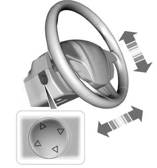
    Adjusting the Steering Wheel - Vehicles With: Power Adjustable Steering Column

    WARNING: Do not adjust the steering wheel when your vehicle is moving.

    Note: Make sure that you are sitting in the correct position.

    Lincoln Corsair. Column

    read more

    Copyright © 2024 www.licorsair.com