Lincoln Corsair: Electronic Engine Controls - 2.0L EcoBoost (177kW/240PS) – MI4 / Removal and Installation - Fuel Rail Pressure (FRP) Sensor
Lincoln Corsair 2020-2024 Service Manual / Powertrain / Engine / Electronic Engine Controls - 2.0L EcoBoost (177kW/240PS) – MI4 / Removal and Installation - Fuel Rail Pressure (FRP) Sensor
Materials
| Name | Specification |
|---|---|
| Motorcraft® Silicone Brake Caliper Grease and Dielectric Compound XG-3-A |
ESA-M1C200-A ESE-M1C171-A |
Removal
NOTE: Removal steps in this procedure may contain installation details.
-
Release the fuel system pressure.
Refer to: Fuel System Pressure Release (310-00A Fuel System - General Information - 2.0L EcoBoost (177kW/240PS) – MI4, General Procedures).
-
Disconnect the battery ground.
Refer to: Battery Disconnect and Connect (414-01 Battery, Mounting and Cables, General Procedures).
-
NOTICE: Do not pull the engine appearance cover forward or sideways to remove. Failure to press straight upward on the underside of the cover at the attachment points may result in damage to the cover or engine components.
-
Remove the engine appearance cover nut.
-
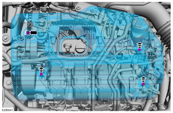
Place your hand under the engine appearance cover at
each grommet location and pull straight up to release each grommet from
the studs.
-
After all of the grommets have been released from the studs, remove the appearance cover from the engine.
-
Remove the engine appearance cover nut.
 |
-
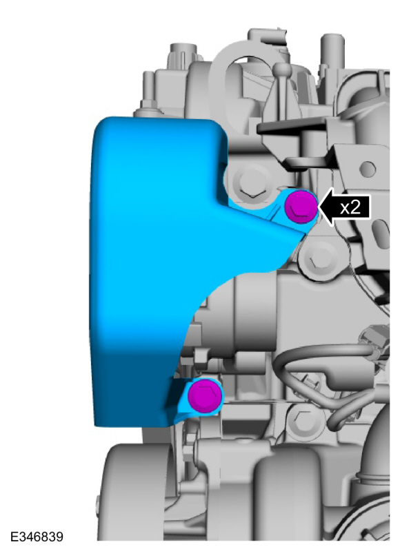
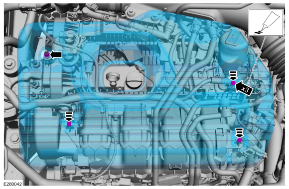
Remove the bolt and remove the safety shield.
Torque: 18 lb.ft (25 Nm)
 |
-
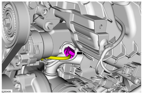
Disconnect the FRP sensor electrical connector.
 |
-
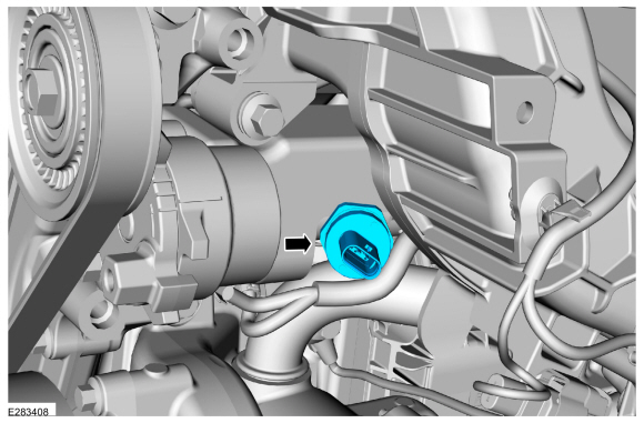
Remove the FRP sensor.
Torque: 24 lb.ft (33 Nm)
 |
Installation
-
To install, reverse the removal procedure.
-
-
NOTE: Lubricating the grommets with silicone grease will aid in the installation of the engine appearance cover, and any future removal and installation of the cover.
Lubricate each grommet with silicone grease.
Material: Motorcraft® Silicone Brake Caliper Grease and Dielectric Compound / XG-3-A (ESA-M1C200-A) (ESE-M1C171-A)
-
Position the engine appearance cover onto engine with the grommets aligned with the studs.
-
Press down on the engine appearance cover at each grommet location to attach the grommets onto the studs.
-
Install the engine appearance cover nut.
Torque: 44 lb.in (5 Nm)
-
If the engine appearance cover stud bolt is loosened
or removed, it must be installed/tightened into the valve cover.
Torque: 62 lb.in (7 Nm)
-
 |
 Removal and Installation - Engine Oil Pressure (EOP) Sensor
Removal
NOTE:
Removal steps in this procedure may contain installation details.
With the vehicle in NEUTRAL, position it on a hoist.
Refer to: Jacking and Lifting - Overview (100-02 Jacking and Lifting, Description and Operation)...
 Removal and Installation - Heated Oxygen Sensor (HO2S)
Special Tool(s) /
General Equipment
303-476
(T94P-9472-A)
Socket, Exhaust Gas Oxygen SensorTKIT-1994-LM/MTKIT-1994-FTKIT-1994-FLM/FM
Materials
Name
Specification
Motorcraft® High Temperature Nickel Anti-Seize LubricantXL-2
-
Motorcraft® Penetrating and Lock LubricantXL-1
-
Removal
NOTICE:
The turbocharger compressor vanes can be damaged by e..
Other information:
Lincoln Corsair 2020-2024 Owners Manual: Liftgate – Troubleshooting
Liftgate – Information Messages Liftgate – Frequently Asked Questions Why won't my power liftgate function? Make sure the transmission is in park (P), ensure nothing is obstructing the liftgate path and there is not excessive weight on the liftgate. If there are continued issues, the battery voltage may be low or other system issues. See an authorized dealer...
Lincoln Corsair 2020-2024 Service Manual: Description and Operation - Battery and Battery Charging Health and Safety Precautions
WARNING: Batteries contain sulfuric acid and produce explosive gases. Work in a well-ventilated area. Do not allow the battery to come in contact with flames, sparks or burning substances. Avoid contact with skin, eyes or clothing. Shield eyes when working near the battery to protect against possible splashing of acid solution. In case of acid contact with skin or eyes, flush immed..
Categories
- Manuals Home
- 1st Generation Lincoln Corsair Owners Manual
- 1st Generation Lincoln Corsair Service Manual
- Auto-Start-Stop
- Selecting a Drive Mode. DRIVE MODES
- Memory Function
- New on site
- Most important about car
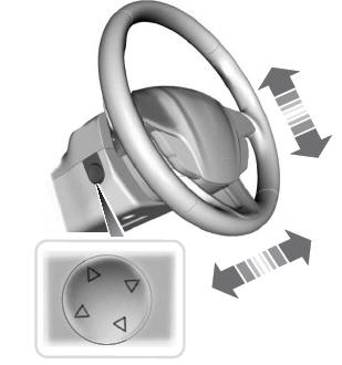
Adjusting the Steering Wheel - Vehicles With: Power Adjustable Steering Column
WARNING: Do not adjust the steering wheel when your vehicle is moving.
Note: Make sure that you are sitting in the correct position.
Copyright © 2024 www.licorsair.com