Lincoln Corsair: Front Drive Halfshafts / Removal and Installation - Front Halfshaft RH - 2.5L Duratec – Hybrid (121kW/164PS) (BG)
Special Tool(s) / General Equipment
 |
204-161
(T97P-1175-A)
Installer, Halfshaft TKIT-1997-LM2 TKIT-1997-F/FM2 TKIT-1997-FLM2 |
 |
205-D070
(D93P-1175-B)
Remover, Front Wheel Hub |
| Tie Rod End Remover | |
Removal
-
Remove the wheel and tire.
Refer to: Wheel and Tire (204-04A Wheels and Tires, Removal and Installation).
-
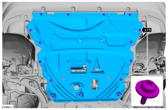
Remove the retainers and the underbody shield.
 |
-
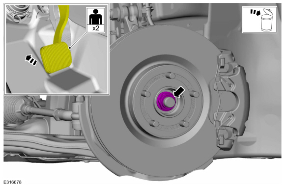
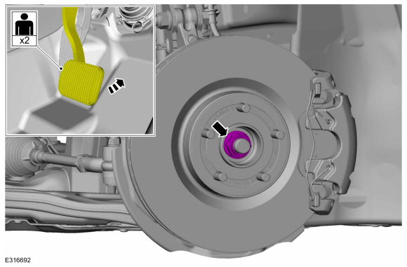
Remove and discard the wheel hub nut.
 |
-
-
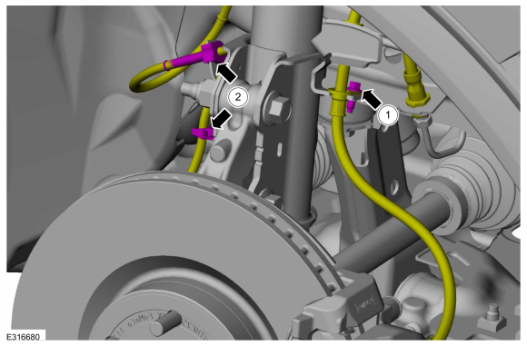
Remove the bolt and position aside the brake hose.
-
Unclip the 2 wire retainers and position aside the wheel speed sensor wiring harness.
-
Remove the bolt and position aside the brake hose.
 |
-
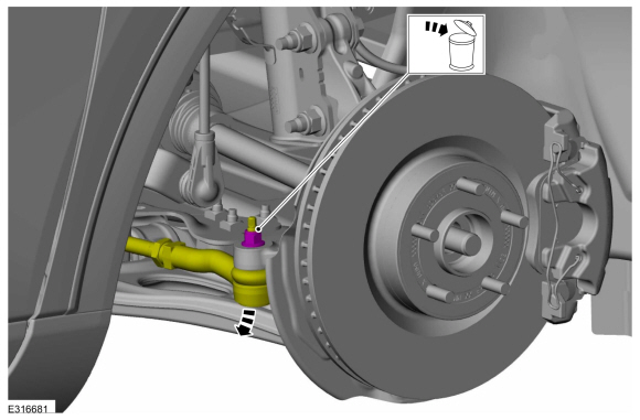
NOTICE: Do not use a hammer to separate the tie rod end from the wheel knuckle or damage to the wheel knuckle may result.
NOTICE: Use care when installing the tie rod separator or damage to the tie rod end boot may occur.
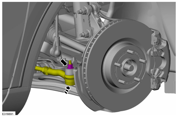
NOTE: Use the hex-holding feature to prevent turning of the stud while removing the tie rod end nut.
Remove and discard the tie rod end nut and separate the tie rod end from the wheel knuckle. Remove the halfshaft.
Use the General Equipment: Tie Rod End Remover
 |
-
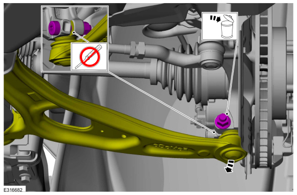
NOTICE: Do not use a prying device to open the slot in the knuckle to separate the lower ball joint from the knuckle assembly. Damage to the knuckle assembly may occur.
NOTICE: Do not use a prying device or separator fork between the ball joint and the wheel knuckle. Damage to the ball joint or ball joint seal may result. Only use the pry bar by inserting it into the lower arm body opening.
NOTICE: Use care when releasing the lower arm and wheel knuckle into the resting position or damage to the ball joint seal may occur.
NOTICE: Do not use power tools to remove or install the lower arm outboard nut. Damage to the ball joint or ball joint seal may occur.
NOTE: Use the TORX PLUS® holding feature to prevent the ball stud from turning while removing or installing the lower arm outboard nut. Torx® and TORX PLUS® is a reg. tm of Acument Intellectual Properties, LLC.
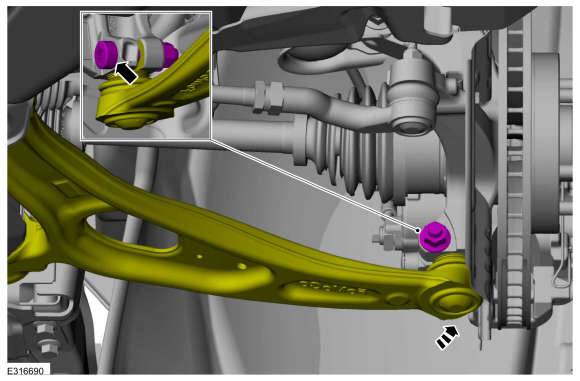
Remove and discard the ball joint pinch bolt and nut and separate the lower arm from the wheel knuckle.
 |
-
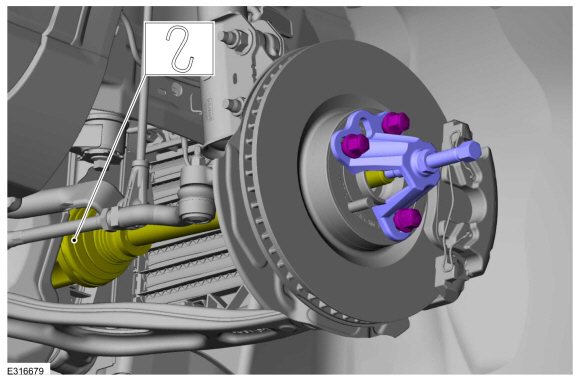
NOTICE: Do not bend the inner joint more than 18 degrees and the outer joint more than 45 degrees. Damage to the shaft will occur.
Using the special tool, press the halfshaft from the wheel bearing and hub. Support the halfshaft in a level position.
Use Special Service Tool: 205-D070 (D93P-1175-B) Remover, Front Wheel Hub.
 |
-
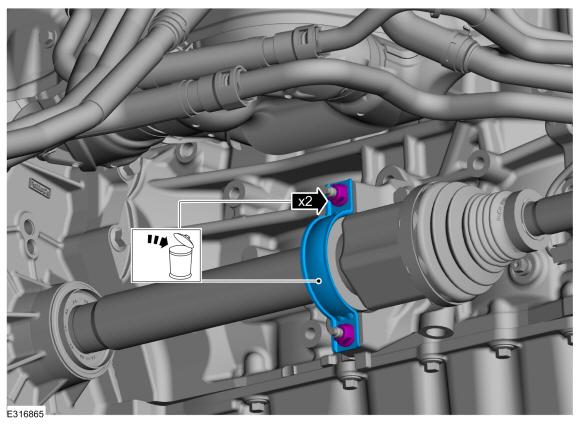
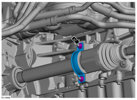
Remove and discard the halfshaft retaining strap and nuts.
 |
-
Remove the halfshaft.
 |
Installation
-
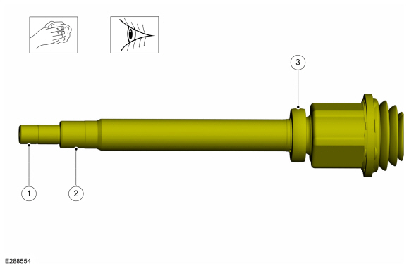
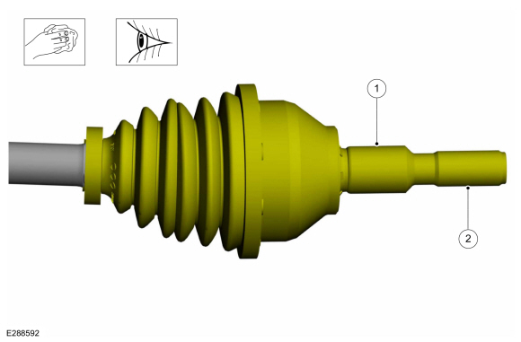
Clean and inspect the inboard end of the halfshaft.
 |
-
Clean and inspect the outboard end of the halfshaft.
 |
-
Install a new halfshaft seal.
Refer to: Halfshaft Seal RH (307-01A Automatic Transmission - 8-Speed Automatic Transmission – 8F35/8F40, Removal and Installation).
Refer to: Halfshaft Seal RH (307-01A Automatic Transmission - 8-Speed Automatic Transmission – 8F35/8F40, Removal and Installation).
-
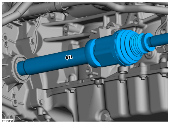
Insert the intermediate shaft until the intermediate
shaft bearing is centered in the concave groove of the intermediate
shaft bearing bracket.
 |
-
Install the new halfshaft retaining strap and nuts.
Torque:
Stage 1: Tighten lower nut to: 44 lb.in (5 Nm)
Stage 2: Tighten upper nut to: 18 lb.ft (25 Nm)
Stage 3: Tighten lower nut to: 18 lb.ft (25 Nm)
 |
-
-
Insert halfshaft through the wheel bearing.
-
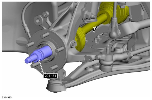
Using the special tool, seat the halfshaft splines in the wheel bearing.
Use Special Service Tool: 204-161 (T97P-1175-A) Installer, Halfshaft.
-
Insert halfshaft through the wheel bearing.
 |
-
NOTICE: Do not use power tools to remove or install the lower arm outboard nut. Damage to the ball joint or ball joint seal may occur.
NOTE: Use the TORX PLUS® holding feature to prevent the ball stud from turning while removing or installing the lower arm outboard nut. Torx® and TORX PLUS® is a reg. tm of Acument Intellectual Properties, LLC.
Position the ball joint into the wheel knuckle and install the new ball joint pinch bolt and nut.
Torque: 81 lb.ft (110 Nm)
 |
-
NOTICE: Use care when installing the tie rod separator or damage to the tie rod end boot may occur.
NOTE: Use the hex-holding feature to prevent turning of the stud while installing the tie rod end nut.
Attach the tie rod end to the wheel knuckle and install the new tie rod end nut.
Torque: 35 lb.ft (48 Nm)
 |
-
-
Position the brake hose and install the bolt.
Torque: 97 lb.in (11 Nm)
-
Position the wheel speed sensor wiring harness and clip the 2 wire retainers.
-
Position the brake hose and install the bolt.
|
-
NOTICE: Do not tighten the front wheel hub nut with the vehicle on the ground. The nut must be tightened to specification before the vehicle is lowered onto the wheels. Wheel bearing damage will occur if the wheel bearing is loaded with the weight of the vehicle applied.
NOTICE: Install and tighten the new wheel hub nut to specification in a continuous rotation. Always install a new wheel hub nut after loosening or when not tightened to specification in a continuous rotation or damage to the components may occur.
NOTE: Apply the brake to keep the halfshaft from rotating.
While an assistant applies the brake, install the new wheel hub nut.
Torque:
Stage 1: 74 lb.ft (100 Nm)
Stage 2: 60°
 |
-
Check the transmission fluid level.
Refer to: Transmission Fluid Level Check (307-01A Automatic Transmission - 8-Speed Automatic Transmission – 8F35/8F40, General Procedures).
Refer to: Transmission Fluid Level Check (307-01B Automatic Transmission - Automatic Transmission – HF45, General Procedures).
Refer to: Transmission Fluid Level Check (307-01B Automatic Transmission - Automatic Transmission – HF45, General Procedures).
-
Install the underbody shield and tighten the retainers.
Torque: 13 lb.in (1.5 Nm)
|
-
Install the wheel and tire.
Refer to: Wheel and Tire (204-04A Wheels and Tires, Removal and Installation).
 Removal and Installation - Front Halfshaft RH - 2.3L EcoBoost (199kW/270PS), FWD
Special Tool(s) /
General Equipment
204-161
(T97P-1175-A)
Installer, HalfshaftTKIT-1997-LM2TKIT-1997-F/FM2TKIT-1997-FLM2
205-D070
(D93P-1175-B)
Remover, Front Wheel Hub
Tie Rod End Remover
Removal
Remove the wheel and tire...
 Removal and Installation - Front Halfshaft RH - AWD
Special Tool(s) /
General Equipment
204-161
(T97P-1175-A)
Installer, HalfshaftTKIT-1997-LM2TKIT-1997-F/FM2TKIT-1997-FLM2
205-D070
(D93P-1175-B)
Remover, Front Wheel Hub
Tie Rod End Remover
Removal
Remove the wheel and tire...
Other information:
Lincoln Corsair 2020-2024 Service Manual: Removal and Installation - Front Seat Power Lumbar Assembly
Removal NOTE: Driver seat shown, passenger seat similar. Remove the front seat. Refer to: Front Seat (501-10A Front Seats, Removal and Installation). Remove the front seat backrest panel. Refer to: Front Seat Backrest Panel (501-10A Front Seats, Removal and Installation)...
Lincoln Corsair 2020-2024 Service Manual: Description and Operation - Power Steering - System Operation and Component Description
System Operation System Diagram Item Description 1 EPAS Column 2 Motor 3 Position sensor 4 Torque sensor 5 PSCM 6 GWM 7 PCM 8 IPC 9 BCM 10 RCM 11 ABS module 12 IPMA 13 PAM 14 SCCM Network Message Chart Module Networ..
Categories
- Manuals Home
- 1st Generation Lincoln Corsair Owners Manual
- 1st Generation Lincoln Corsair Service Manual
- Remote Start Settings
- Automatic Transmission - 8-Speed Automatic Transmission – 8F35/8F40
- Warning Lamps and Indicators
- New on site
- Most important about car
Keyless Starting
Note: The keyless starting system may not function if the key is close to metal objects or electronic devices such as cellular phones.
Note: A valid key must be located inside your vehicle to switch the ignition on and start the engine.
Ignition Modes