Lincoln Corsair: Handles, Locks, Latches and Entry Systems / Removal and Installation - Exterior Front Door Handle Reinforcement
Lincoln Corsair 2020-2024 Service Manual / Body and Paint / Body and Paint / Handles, Locks, Latches and Entry Systems / Removal and Installation - Exterior Front Door Handle Reinforcement
Removal
NOTE: LH (left-hand) side shown, RH (right-hand) side similar.
-
Remove the front door latch.
Refer to: Front Door Latch (501-14 Handles, Locks, Latches and Entry Systems, Removal and Installation).
-
NOTE: This step is only necessary when installing a new component.
Release the cable tension by turning the release screw until the handle lever releases from the stop.
-
Turn the release screw until the handle lever releases from the stop.
-
Release the handle lever from the stop.
-
Turn the release screw until the handle lever releases from the stop.
.jpg) |
-
NOTE: This step is only necessary when installing a new component.
Remove the exterior front door handle reinforcement.
-
Detach the cable from the exterior front door handle reinforcement cable bracket.
-
Remove the cable eyelet from the lever.
-
Press the locking tab down.
-
Detach the exterior front door handle reinforcement.
-
If equipped, disconnect the door lock cylinder rod.
Remove the exterior front door handle reinforcement.
-
Detach the cable from the exterior front door handle reinforcement cable bracket.
.jpg) |
Installation
-
To install, reverse the removal procedure.
-
NOTE: This step is only necessary when installing a new component.
NOTE: This step must be done correctly or the exterior door handle will not engage the lever on installation.
Position the exterior front door handle reinforcement in the service position.
-
While keeping tension on the cable and holding the handle lever in the engaged position against the stop.
-
Turn the release screw until the handle lever is positioned against the stop.
-
While keeping tension on the cable and holding the handle lever in the engaged position against the stop.
.jpg) |
-
Carry out the power door window initialization.
Refer to: Power Door Window Initialization (501-11 Glass, Frames and Mechanisms, General Procedures).
 Removal and Installation - Exterior Front Door Handle
Removal
NOTE:
LH (left-hand) side shown, RH (right-hand) side similar.
NOTE:
Removal steps in this procedure may contain installation details.
Remove the front door window regulator and motor...
 Removal and Installation - Exterior Rear Door Handle
Removal
NOTE:
LH (left-hand) side shown, RH (right-hand) side similar.
NOTE:
Removal steps in this procedure may contain installation details.
Remove the rear door window regulator and motor...
Other information:
Lincoln Corsair 2020-2024 Service Manual: Description and Operation - Starting System - System Operation and Component Description
System Operation System Diagram Item Description 1 PCM 2 Starter relay 3 Starter motor 4 BCM 5 Automatic transmission 6 Ignition switch Network Message Chart Module Network Input Messages Powertrain Control Module (PCM) Broadcast Message Originating Modul..
Lincoln Corsair 2020-2024 Owners Manual: RADIO FREQUENCY CERTIFICATION LABELS
Blind Spot Information System Sensors Argentina Brazil China CMIIT ID: 2015DJ1610 Djibouti European Union EU Ghana Jamaica Malaysia RALM/24A/0715/S(15-2272) Mauritania Moldova Pakistan Paraguay Serbia Singapore South Africa South Korea MSIP-CRM-8DC-SRR3B Taiwan, China Ukraine United Arab Emirates (U.A.E.) United States and Canada WARNING: Changes or modifications not expressive..
Categories
- Manuals Home
- 1st Generation Lincoln Corsair Owners Manual
- 1st Generation Lincoln Corsair Service Manual
- Head Up Display
- Refueling - Gasoline
- Automatic Transmission - 8-Speed Automatic Transmission – 8F35/8F40
- New on site
- Most important about car
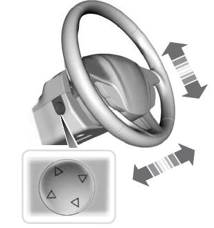
Adjusting the Steering Wheel - Vehicles With: Power Adjustable Steering Column
WARNING: Do not adjust the steering wheel when your vehicle is moving.
Note: Make sure that you are sitting in the correct position.
Copyright © 2024 www.licorsair.com