Lincoln Corsair: Anti-Lock Brake System (ABS) and Stability Control / Removal and Installation - Electric Brake Booster (EBB)
Removal
NOTE: Removal steps in this procedure may contain installation details.
NOTE: The EBB and the ABS module are serviced as an assembly and should not be separated.
-
NOTE: The PMI process must begin with the current ABS module installed. If the current ABS module does not respond to the diagnostic scan tool, the tool may prompt for As-Built Data as part of the repair.
Using a diagnostic scan tool, begin the PMI process for the ABS module following the onscreen instructions.
-
Remove the battery tray.
Refer to: Battery Tray - 2.0L EcoBoost (177kW/240PS) – MI4/2.3L EcoBoost (199kW/270PS) (414-01 Battery, Mounting and Cables, Removal and Installation).
-
Remove the battery tray reinforcment.
 |
-
Detach the cable retainer, remove the bolts and the battery tray reinforcment bracket.
Torque: 133 lb.in (15 Nm)
 |
-
Remove the center cowl insulation panel bolt and the coolant hose cover.
Torque: 71 lb.in (8 Nm)
 |
-
Remove the nuts and the center cowl insulation panel.
Torque: 71 lb.in (8 Nm)
 |
-
Remove the nuts and the LH cowl insulation panel.
Torque: 71 lb.in (8 Nm)
 |
-
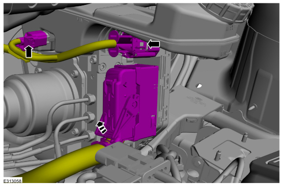
Disconnect the electrical connectors.
 |
-
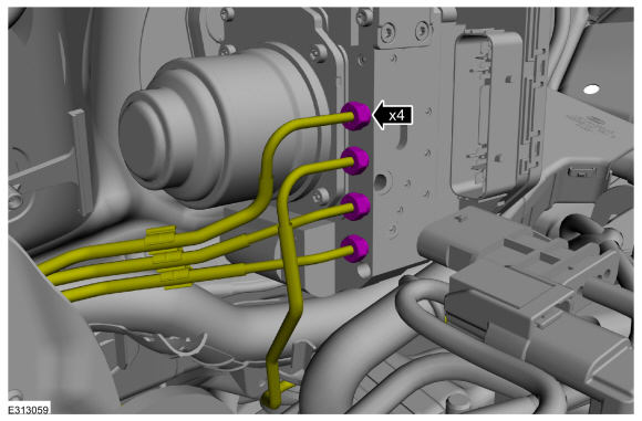
NOTICE: If the brake fluid is spilled on any component, the affected area must be immediately washed down with cold water.
NOTE: Make sure that all openings are sealed.
Disconnect the brake tube fittings.
Torque: 159 lb.in (18 Nm)
 |
-
Remove the stoplamp switch.
Refer to: Stoplamp Switch (417-01 Exterior Lighting, Removal and Installation).
-
Push inward on the tabs and remove the clevis pin. Discard the pin.
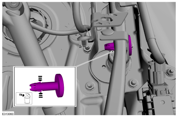 |
-
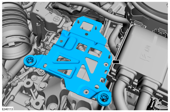
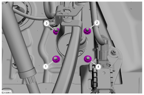
Remove the EBB nuts in the order shown.
Torque: 177 lb.in (20 Nm)
 |
-
Remove the the EBB .
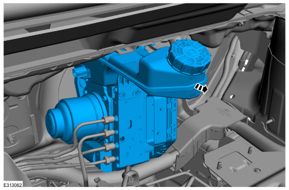 |
Installation
-
To install, reverse the removal procedure.
-
Using a diagnostic scan tool, complete the PMI process for the ABS module following the on-screen instructions.
-
Carry out the following service functions using the scan
tool and following the diagnostic scan tool on-screen instructions.
-
Carry out the ABS Brake System Pressure Bleeding and Bleed Check.
-
Carry out the ABS Calibration.
-
Carry out the EPB initialization.
-
Run the PCM
PATS
programming application and then carry out the Module Initialization
(Parameter Reset) using the scan tool and following the diagnostic scan
tool on-screen instructions.
-
Carry out the ABS Brake System Pressure Bleeding and Bleed Check.
 Diagnosis and Testing - Anti-Lock Brake System (ABS) and Stability Control
Diagnostic Trouble Code (DTC) Chart
Diagnostics in this manual assume a certain skill level and knowledge of Ford-specific diagnostic practices. REFER to: Diagnostic Methods (100-00 General Information, Description and Operation)...
 Removal and Installation - Electric Brake Booster (EBB) - Plug-In Hybrid Electric Vehicle (PHEV)
Removal
NOTE:
Removal steps in this procedure may contain installation details.
NOTE:
The EBB and the ABS module are serviced as an assembly and should not be separated...
Other information:
Lincoln Corsair 2020-2024 Service Manual: Removal and Installation - Headliner - Lowering
Special Tool(s) / General Equipment Pick Hook Interior Trim Remover Remove the following items: On both sides. Remove the A-pillar trim panel. Refer to: A-Pillar Trim Panel (501-05 Interior Trim and Ornamentation, Removal and Installation)...
Lincoln Corsair 2020-2024 Owners Manual: Tire Sealant and Inflator Kit (IF EQUIPPED)
Note: The temporary mobility kit contains enough sealant compound in the canister for one tire repair only. See your authorized Ford dealer for replacement sealant canisters. The kit is located under the load floor in the trunk. The kit consists of an air compressor to re-inflate the tire and a canister of sealing compound that will effectively seal most punctures caused by nails or simila..
Categories
- Manuals Home
- 1st Generation Lincoln Corsair Owners Manual
- 1st Generation Lincoln Corsair Service Manual
- Opening and Closing the Hood
- Auto-Start-Stop
- Warning Lamps and Indicators
- New on site
- Most important about car
Second Stage: Checking Tire Pressure
WARNING: If the tire does not inflate to the recommended tire pressure within 15 minutes, stop and call roadside assistance.
WARNING: The power plug may get hot after use and should be handled carefully when unplugging.
Check the air pressure of your tires as follows: