Lincoln Corsair: Accessory Drive - 2.0L EcoBoost (177kW/240PS) – MI4 / Removal and Installation - Accessory Drive Belt Tensioner
Materials
| Name | Specification |
|---|---|
| Motorcraft® Silicone Brake Caliper Grease and Dielectric Compound XG-3-A |
ESA-M1C200-A ESE-M1C171-A |
Removal
NOTICE: Under no circumstances should the accessory drive belt, tensioner or pulleys be lubricated as potential damage to the belt material and tensioner damping mechanism will occur. Do not apply any fluids or belt dressing to the accessory drive belt or pulleys.
NOTE: Removal steps in this procedure may contain installation details.
-
NOTICE: Do not pull the engine appearance cover forward or sideways to remove. Failure to press straight upward on the underside of the cover at the attachment points may result in damage to the cover or engine components.
-
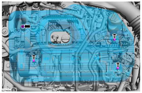
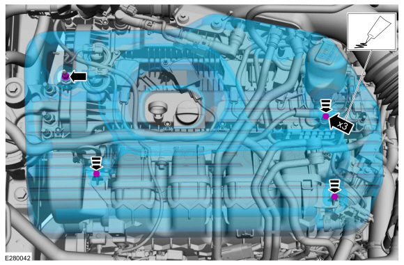
Remove the engine appearance cover nut.
Torque: 89 lb.in (10 Nm)
-
Place your hand under the engine appearance cover at
each grommet location and push straight up to release each grommet from
the studs.
-
After all of the grommets have been released from the studs, remove the appearance cover from the engine.
-
Remove the engine appearance cover nut.
 |
-
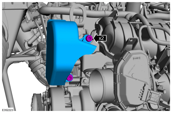
Remove the bolt and the shield.
Torque: 18 lb.ft (25 Nm)
 |
-
NOTE: After installation, make sure the accessory drive belt is correctly seated on all the pulleys.
-
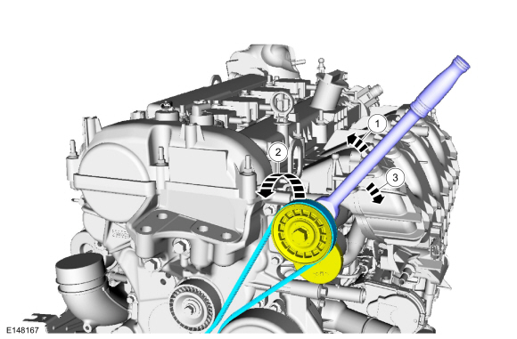
Rotate the accessory drive belt tensioner counter clockwise.
-
Remove the accessory drive belt from the accessory drive belt tensioner pulley.
-
Release the accessory drive belt tensioner and remove the accessory drive belt.
-
Rotate the accessory drive belt tensioner counter clockwise.
 |
-
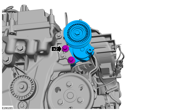
NOTE: The accessory drive belt tensioner must be replaced as a complete unit.
-
Loosen the bolts and remove the accessory drive belt tensioner.
Torque: 18 lb.ft (25 Nm)
-
Loosen the bolts and remove the accessory drive belt tensioner.
 |
Installation
-
NOTE: Safety shield must be re-installed, to protect hands in the case of an un-expected start.
To install, reverse the removal procedure.
-
Install the bolt and the shield.
Torque: 18 lb.ft (25 Nm)
|
-
-
NOTE: Lubricating the grommets with silicone grease will aid in the installation of the engine appearance cover, and any future removal and installation of the cover.
Lubricate each grommet with silicone grease.
Material: Motorcraft® Silicone Brake Caliper Grease and Dielectric Compound / XG-3-A (ESA-M1C200-A) (ESE-M1C171-A)
-
If the engine appearance cover stud bolt is loosened
or removed, it must be installed/tightened into the valve cover.
Torque: 62 lb.in (7 Nm)
-
Position the engine appearance cover onto engine with the grommets aligned with the studs.
-
Press down on the engine appearance cover at each grommet location to attach the grommets onto the studs.
-
Install the engine appearance cover nut.
Torque: 44 lb.in (5 Nm)
-
 |
 Removal and Installation - Accessory Drive Belt Idler Pulley
Materials
Name
Specification
Motorcraft® Silicone Brake Caliper Grease and Dielectric CompoundXG-3-A
ESA-M1C200-AESE-M1C171-A
Removal
NOTICE:
Do not pull the engine appearance cover forward or
sideways to remove...
 Removal and Installation - Air Conditioning (A/C) Compressor Belt
Special Tool(s) /
General Equipment
303-1252Stretchy Belt Remover/ Installer ToolTKIT-2006UF-FLMTKIT-2006UF-ROW
Knife
Removal
NOTICE:
Under no circumstances should the accessory drive belt,
tensioner or pulleys be lubricated as potential damage to the belt
material and tensioner damping mechanism will occur...
Other information:
Lincoln Corsair 2020-2024 Service Manual: General Procedures - Wheel to Tire Runout Minimization
Check NOTICE: Non-Hunter brand balancers will not include the Ford-approved procedure for match-mounting in their software. NOTICE: Other balancing procedures that exist on non-Hunter brand equipment are not Ford approved and should not be used...
Lincoln Corsair 2020-2024 Service Manual: General Procedures - Clockspring Adjustment
Special Tool(s) / General Equipment Adhesive Tape WARNING: If the clockspring is not correctly centralized, it may fail prematurely. If in doubt, repeat the centralizing procedure. Failure to follow these instructions may increase the risk of serious personal injury or death in a crash...
Categories
- Manuals Home
- 1st Generation Lincoln Corsair Owners Manual
- 1st Generation Lincoln Corsair Service Manual
- Changing a Road Wheel
- Programming the Garage Door Opener to Your Garage Door Opener Motor
- Selecting a Drive Mode. DRIVE MODES
- New on site
- Most important about car
Creating a Vehicle Wi-Fi Hotspot
You can create a Wi-Fi hotspot in your vehicle and allow devices to connect to it for access to the Internet.
 Select the settings option on
the
feature bar.
Select the settings option on
the
feature bar.