Lincoln Corsair: Electronic Engine Controls - 2.0L EcoBoost (177kW/240PS) – MI4 / Diagnosis and Testing - Powertrain Control Module (PCM) Input and Output Controls
Diagnostic Trouble Code (DTC) Chart
Diagnostics in this manual assume a certain skill level and knowledge of Ford-specific diagnostic practices.
REFER to: Diagnostic Methods (100-00 General Information, Description and Operation).
| Module | DTC | Description | Action |
|---|---|---|---|
| PCM | P0219:00 | Engine Overspeed Condition: No Sub Type Information | GO to Pinpoint Test Z |
| PCM | P0297:00 | Vehicle Overspeed Condition: No Sub Type Information | GO to Pinpoint Test Z |
| PCM | P0603:00 | Internal Control Module Keep Alive Memory (KAM) Error: No Sub Type Information | GO to Pinpoint Test QB |
| PCM | P0642:00 | Sensor Reference Voltage 'A' Circuit Low: No Sub Type Information | GO to Pinpoint Test C |
| PCM | P0643:00 | Sensor Reference Voltage 'A' Circuit High: No Sub Type Information | GO to Pinpoint Test C |
| PCM | P0652:00 | Sensor Reference Voltage 'B' Circuit Low: No Sub Type Information | GO to Pinpoint Test C |
| PCM | P0653:00 | Sensor Reference Voltage 'B' Circuit High: No Sub Type Information | GO to Pinpoint Test C |
| PCM | P0685:00 | ECM/PCM Power Relay Control Circuit/Open: No Sub Type Information | GO to Pinpoint Test B |
| PCM | P0686:00 | ECM/PCM Power Relay Control Circuit Low: No Sub Type Information | GO to Pinpoint Test B |
| PCM | P0687:00 | ECM/PCM Power Relay Control Circuit High: No Sub Type Information | GO to Pinpoint Test B |
| PCM | P0689:00 | ECM/PCM Power Relay Sense Circuit Low: No Sub Type Information | GO to Pinpoint Test B |
| PCM | P068A:00 | ECM/PCM Power Relay De-Energized - Too Early: No Sub Type Information | GO to Pinpoint Test B |
| PCM | P0690:00 | ECM/PCM Power Relay Sense Circuit High: No Sub Type Information | GO to Pinpoint Test B |
| PCM | P06A6:00 | Sensor Reference Voltage 'A' Circuit Range/Performance: No Sub Type Information | GO to Pinpoint Test C |
| PCM | P06A7:00 | Sensor Reference Voltage 'B' Circuit Range/Performance: No Sub Type Information | GO to Pinpoint Test C |
| PCM | P06A8:00 | Sensor Reference Voltage 'C' Circuit Range/Performance: No Sub Type Information | GO to Pinpoint Test C |
| PCM | P06B8:00 | Internal Control Module Non-Volatile Random Access Memory (NVRAM) Error: No Sub Type Information | GO to Pinpoint Test B |
| PCM | P1633:00 | Keep Alive Power Voltage Too Low: No Sub Type Information | GO to Pinpoint Test QB |
| PCM | P1793:00 | Ignition Supply Malfunction >16, <7 volts: No Sub Type Information | GO to Pinpoint Test B |
| PCM | P2510:00 | ECM / PCM Power Relay Sense Circuit Range/Performance: No Sub Type Information | GO to Pinpoint Test B |
| PCM | P2610:00 | ECM/PCM Engine Off Timer Performance: No Sub Type Information | GO to Pinpoint Test QB |
| PCM | U300C:00 | Ignition Input Off/On/Start: No Sub Type Information | GO to Pinpoint Test B |
Global Customer Symptom Code (GCSC) Chart
Diagnostics in this manual assume a certain skill level and knowledge of Ford-specific diagnostic practices.
REFER to: Diagnostic Methods (100-00 General Information, Description and Operation).
| Symptom | Action |
|---|---|
| Driver Aid & Information > Warning Indicators/Messages/Chimes > Electronic Throttle Control (Wrench Image) > Stays On | GO to Pinpoint Test Z |
| Driver Aid & Information > Warning Indicators/Messages/Chimes > Service Engine Soon (Engine Image) > Stays On | GO to Pinpoint Test Z |
| Driver Aid & Information > Warning Indicators/Messages/Chimes > Transmission > Stays On | GO to Pinpoint Test Z |
| Start/Run/Move > Starting > No Crank > Always | GO to Pinpoint Test C |
| Start/Run/Move > Starting > No Crank > Intermittent | GO to Pinpoint Test Z |
| Start/Run/Move > Starting > Slow Crank/Battery > Intermittent | GO to Pinpoint Test Z |
| Start/Run/Move > Starting > Hard Start/Long Crank > Always | GO to Pinpoint Test C |
| Start/Run/Move > Starting > Hard Start/Long Crank > Intermittent | GO to Pinpoint Test Z |
| Start/Run/Move > Starting > Auto-Start-Stop > Inoperative | GO to Pinpoint Test Z |
| Start/Run/Move > Running > Engine Won't Shut Off > Always | GO to Pinpoint Test B |
| Start/Run/Move > Moving > Upshift Quality > Intermittent | GO to Pinpoint Test Z |
| Start/Run/Move > Moving > Downshift Quality > Intermittent | GO to Pinpoint Test Z |
| Driving Performance > Runs Rough > All Running Modes > Intermittent | GO to Pinpoint Test Z |
| Driving Performance > Idle Quality > Rolling > Intermittent | GO to Pinpoint Test Z |
| Driving Performance > Stalls/Quits > At Idle > Intermittent | GO to Pinpoint Test Z |
| Driving Performance > Backfires > At Idle > Intermittent | GO to Pinpoint Test Z |
| Driving Performance > Backfires > Acceleration > Intermittent | GO to Pinpoint Test Z |
| Driving Performance > Backfires > Deceleration > Intermittent | GO to Pinpoint Test Z |
| Driving Performance > Lack/Loss of Power > Acceleration > Intermittent | GO to Pinpoint Test Z |
| Driving Performance > Lack/Loss of Power > Cruise/ Steady Speed > Intermittent | GO to Pinpoint Test Z |
| Driving Performance > Spark Knock > Acceleration > Intermittent | GO to Pinpoint Test Z |
| Driving Performance > Spark Knock > Cruise/ Steady Speed > Intermittent | GO to Pinpoint Test Z |
| Driving Performance > Poor Fuel Economy > Highway Driving > Unloaded | GO to Pinpoint Test Z |
| Driving Performance > Poor Fuel Economy > Combined > Unloaded | GO to Pinpoint Test Z |
| Driving Performance > Hesitates/Stumble > Acceleration > Intermittent | GO to Pinpoint Test Z |
| Driving Performance > Hesitates/Stumble > Cruise/ Steady Speed > Intermittent | GO to Pinpoint Test Z |
Pinpoint Tests


 Introduction Introduction
Normal Operation and Fault Conditions Refer to the DTC Fault Trigger Conditions. DTC Fault Trigger Conditions
Possible Sources
|
 Introduction
| Introduction
Normal Operation and Fault Conditions Refer to the DTC Fault Trigger Conditions. DTC Fault Trigger Conditions
Possible Sources
|
| Introduction
Normal Operation and Fault Conditions Refer to the DTC Fault Trigger Conditions. DTC Fault Trigger Conditions
Possible Sources
|
| Introduction
Normal Operation and Fault Conditions This pinpoint test is intended to diagnose and isolate intermittent concerns for all EEC subsystems. Parameter identifiers (PIDs) corresponding to a circuit can be used to aid in identifying the intermittent cause. Some circuits do not have an associated PID or the PID may not be available and must be measured using a digital multimeter. Refer to the DTC Fault Trigger Conditions. DTC Fault Trigger Conditions
Possible Sources
|
 Diagnosis and Testing - Engine Starting Control System
Diagnostic Trouble Code (DTC) Chart
Diagnostics in this manual assume a certain skill level and knowledge of Ford-specific diagnostic practices. REFER to: Diagnostic Methods (100-00 General Information, Description and Operation)...
 Diagnosis and Testing - Variable Camshaft Timing (VCT) System
Diagnostic Trouble Code (DTC) Chart
Diagnostics in this manual assume a certain skill level and knowledge of Ford-specific diagnostic practices.REFER to: Diagnostic Methods (100-00 General Information, Description and Operation)...
Other information:
Lincoln Corsair 2020-2024 Service Manual: Removal and Installation - Front Door Side Impact Sensor
Removal WARNING: The following procedure prescribes critical repair steps required for correct restraint system operation during a crash. Follow all notes and steps carefully. Failure to follow step instructions may result in incorrect operation of the restraint system and increases the risk of serious personal injury or death in a crash...
Lincoln Corsair 2020-2024 Service Manual: Removal and Installation - Hands-Free Liftgate Actuation Lower Sensor
Removal NOTE: Removal steps in this procedure may contain installation details. With the vehicle in NEUTRAL, position it on a hoist. Refer to: Jacking and Lifting (100-02) . Remove the push pins, the screws and the lower bumper cover bracket assembly...
Categories
- Manuals Home
- 1st Generation Lincoln Corsair Owners Manual
- 1st Generation Lincoln Corsair Service Manual
- Keyless Entry Settings
- Fuel Quality - Gasoline
- Normal Scheduled Maintenance
- New on site
- Most important about car
Information on P Type Tires
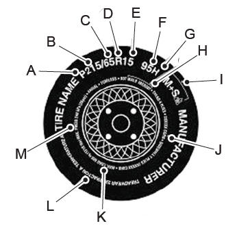
P215/65R15 95H is an example of a tire size, load index and speed rating. The definitions of these items are listed below. (Note that the tire size, load index and speed rating for your vehicle may be different from this example.)
P: Indicates a tire, designated by the Tire and Rim Association, that may be used for service on cars, sport utility vehicles, minivans and light trucks. Note: If your tire size does not begin with a letter this may mean it is designated by either the European Tire and Rim Technical Organization or the Japan Tire Manufacturing Association. 215: Indicates the nominal width of the tire in millimeters from sidewall edge to sidewall edge. In general, the larger the number, the wider the tire. 65: Indicates the aspect ratio which gives the tire's ratio of height to width. R: Indicates a radial type tire. 15: Indicates the wheel or rim diameter in inches. If you change your wheel size, you will have to purchase new tires to match the new wheel diameter. 95: Indicates the tire's load index. It is an index that relates to how much weight a tire can carry. You may find this information in your owner’s manual. If not, contact a local tire dealer.