Lincoln Corsair: Anti-Lock Brake System (ABS) and Stability Control / Diagnosis and Testing - Anti-Lock Brake System (ABS) and Stability Control
Diagnostic Trouble Code (DTC) Chart
Diagnostics in this manual assume a certain skill level and knowledge of Ford-specific diagnostic practices.
REFER to: Diagnostic Methods (100-00 General Information, Description and Operation).
| Module | DTC | Description | Action |
|---|---|---|---|
| ABS | C0020:11 | ABS Pump Motor Control: Circuit Short To Ground | GO to Pinpoint Test H |
| ABS | C0020:12 | ABS Pump Motor Control: Circuit Short To Battery | GO to Pinpoint Test H |
| ABS | C0020:13 | ABS Pump Motor Control: Circuit Open | GO to Pinpoint Test H |
| ABS | C0020:49 | ABS Pump Motor Control: Internal Electronic Failure | GO to Pinpoint Test H |
| ABS | C0020:71 | ABS Pump Motor Control: Actuator Stuck | GO to Pinpoint Test H |
| ABS | C0030:07 | Left Front Tone Wheel: Mechanical Failures | GO to Pinpoint Test AB |
| ABS | C0031:01 | Left Front Wheel Speed Sensor: General Electrical Failure | GO to Pinpoint Test M |
| ABS | C0031:07 | Left Front Wheel Speed Sensor: Mechanical Failures | GO to Pinpoint Test AB |
| ABS | C0031:2F | Left Front Wheel Speed Sensor: Signal Erratic | GO to Pinpoint Test AB |
| ABS | C0031:4A | Left Front Wheel Speed Sensor: Incorrect Component Installed | GO to Pinpoint Test AL |
| ABS | C0031:64 | Left Front Wheel Speed Sensor: Signal Plausibility Failure | GO to Pinpoint Test AB |
| ABS | C0033:07 | Right Front Tone Wheel: Mechanical Failures | GO to Pinpoint Test AB |
| ABS | C0034:01 | Right Front Wheel Speed Sensor: General Electrical Failure | GO to Pinpoint Test M |
| ABS | C0034:07 | Right Front Wheel Speed Sensor: Mechanical Failures | GO to Pinpoint Test AB |
| ABS | C0034:2F | Right Front Wheel Speed Sensor: Signal Erratic | GO to Pinpoint Test AB |
| ABS | C0034:4A | Right Front Wheel Speed Sensor: Incorrect Component Installed | GO to Pinpoint Test AL |
| ABS | C0034:64 | Right Front Wheel Speed Sensor: Signal Plausibility Failure | GO to Pinpoint Test AB |
| ABS | C0036:07 | Left Rear Tone Wheel: Mechanical Failures | GO to Pinpoint Test AB |
| ABS | C0037:01 | Left Rear Wheel Speed Sensor: General Electrical Failure | GO to Pinpoint Test N |
| ABS | C0037:07 | Left Rear Wheel Speed Sensor: Mechanical Failures | GO to Pinpoint Test AB |
| ABS | C0037:2F | Left Rear Wheel Speed Sensor: Signal Erratic | GO to Pinpoint Test AB |
| ABS | C0037:4A | Left Rear Wheel Speed Sensor: Incorrect Component Installed | GO to Pinpoint Test AL |
| ABS | C0037:64 | Left Rear Wheel Speed Sensor: Signal Plausibility Failure | GO to Pinpoint Test AB |
| ABS | C0039:07 | Right Rear Tone Wheel: Mechanical Failures | GO to Pinpoint Test AB |
| ABS | C003A:01 | Right Rear Wheel Speed Sensor: General Electrical Failure | GO to Pinpoint Test N |
| ABS | C003A:07 | Right Rear Wheel Speed Sensor: Mechanical Failures | GO to Pinpoint Test AB |
| ABS | C003A:2F | Right Rear Wheel Speed Sensor: Signal Erratic | GO to Pinpoint Test AB |
| ABS | C003A:4A | Right Rear Wheel Speed Sensor: Incorrect Component Installed | GO to Pinpoint Test AL |
| ABS | C003A:64 | Right Rear Wheel Speed Sensor: Signal Plausibility Failure | GO to Pinpoint Test AB |
| ABS | C0040:64 | Brake Pedal Switch 'A': Signal Plausibility Failure | GO to Pinpoint Test CO |
| ABS | C0044:49 | Brake Pressure Sensor 'A': Internal Electronic Failure | GO to Pinpoint Test AM |
| ABS | C0044:51 | Brake Pressure Sensor 'A': Not Programmed | GO to Pinpoint Test AM |
| ABS | C0044:64 | Brake Pressure Sensor 'A': Signal Plausibility Failure | GO to Pinpoint Test AM |
| ABS | C0044:8F | Brake Pressure Sensor 'A': Erratic | GO to Pinpoint Test AM |
| ABS | C0047:1C | Brake Booster Pressure Sensor: Circuit Voltage Out Of Range | GO to Pinpoint Test CO |
| ABS | C0047:64 | Brake Booster Pressure Sensor: Signal Plausibility Failure | GO to Pinpoint Test CO |
| ABS | C0049:01 | Brake Fluid Level: General Electrical Failure | GO to Pinpoint Test I |
| ABS | C0049:7A | Brake Fluid Level: Fluid Leak Or Seal Failure | GO to Pinpoint Test I |
| ABS | C0049:7B | Brake Fluid Level: Low Fluid Level | GO to Pinpoint Test I |
| ABS | C0051:64 | Steering Wheel Position Sensor: Signal Plausibility Failure | GO to Pinpoint Test LA |
| ABS | C0051:67 | Steering Wheel Position Sensor: Signal Incorrect After Event | GO to Pinpoint Test LA |
| ABS | C0051:85 | Steering Wheel Position Sensor: Signal Above Allowable Range | GO to Pinpoint Test LA |
| ABS | C0051:86 | Steering Wheel Position Sensor: Signal Invalid | GO to Pinpoint Test LA |
| ABS | C0061:28 | Lateral Acceleration Sensor: Signal Bias Level Out Of Range/Zero Adjustment Failure | GO to Pinpoint Test AG |
| ABS | C0061:54 | Lateral Acceleration Sensor: Missing Calibration | GO to Pinpoint Test AN |
| ABS | C0061:64 | Lateral Acceleration Sensor: Signal Plausibility Failure | GO to Pinpoint Test AG |
| ABS | C0062:28 | Longitudinal Acceleration Sensor: Signal Bias Level Out Of Range/Zero Adjustment Failure | GO to Pinpoint Test AG |
| ABS | C0062:54 | Longitudinal Acceleration Sensor: Missing Calibration | GO to Pinpoint Test AN |
| ABS | C0062:64 | Longitudinal Acceleration Sensor: Signal Plausibility Failure | GO to Pinpoint Test AG |
| ABS | C0063:28 | Yaw Rate Sensor: Signal Bias Level Out Of Range/Zero Adjustment Failure | GO to Pinpoint Test AG |
| ABS | C0063:64 | Yaw Rate Sensor: Signal Plausibility Failure | GO to Pinpoint Test AG |
| ABS | C0064:28 | Roll Rate Sensor: Signal Bias Level Out Of Range/Zero Adjustment Failure | GO to Pinpoint Test AG |
| ABS | C0064:64 | Roll Rate Sensor: Signal Plausibility Failure | GO to Pinpoint Test AG |
| ABS | C006A:95 | Multi-axis Acceleration Sensor: Incorrect Assembly | GO to Pinpoint Test AN |
| ABS | C006B:00 | Stability System Active Too Long: No Sub Type Information | GO to Pinpoint Test AD |
| ABS | C0078:00 | Tire Diameter: No Sub Type Information | GO to Pinpoint Test ZA |
| ABS | C052E:A2 | ABS Pump Motor Control Circuit Low: System Voltage Low | GO to Pinpoint Test H |
| ABS | C0594:12 | Brake Booster Motor 'A' Performance: Circuit Short To Battery | GO to Pinpoint Test CP |
| ABS | C0594:78 | Brake Booster Motor 'A' Performance: Alignment Or Adjustment Incorrect | GO to Pinpoint Test CP |
| ABS | C0594:92 | Brake Booster Motor 'A' Performance: Performance Or Incorrect Operation | GO to Pinpoint Test CP |
| ABS | C0596:00 | Brake Booster Motor 'A' Current Sensor Circuit Range/Performance: No Sub Type Information | GO to Pinpoint Test CP |
| ABS | C1013:09 | Brake System Pressure: Component Failures | GO to Pinpoint Test CO |
| ABS | C1013:7A | Brake System Pressure: Fluid Leak Or Seal Failure | GO to Pinpoint Test CO |
| ABS | C1013:7C | Brake System Pressure: Slow Response | GO to Pinpoint Test CO |
| ABS | C1013:92 | Brake System Pressure: Performance Or Incorrect Operation | GO to Pinpoint Test CO |
| ABS | C1018:61 | Regenerative Braking: Signal Calculation Failure | GO to Pinpoint Test Z |
| ABS | C1019:29 | Linear Actuator Control (LAC): Signal Invalid | GO to Pinpoint Test CO |
| ABS | C1019:78 | Linear Actuator Control (LAC): Alignment Or Adjustment Incorrect | GO to Pinpoint Test CO |
| ABS | C1019:92 | Linear Actuator Control (LAC): Performance Or Incorrect Operation | GO to Pinpoint Test CO |
| ABS | C101F:46 | Generic Valve Failure: Calibration/Parameter Memory Failure | GO to Pinpoint Test Z |
| ABS | C101F:49 | Generic Valve Failure: Internal Electronic Failure | GO to Pinpoint Test Z |
| ABS | C1020:00 | Brake System Fill Not Complete: No Sub Type Information | GO to Pinpoint Test J |
| ABS | C1020:52 | Brake System Fill Not Complete: Not Activated | GO to Pinpoint Test J |
| ABS | C1109:64 | Vehicle Dynamics Control Switch: Signal Plausibility Failure | GO to Pinpoint Test O |
| ABS | C1A08:1C | Pressure Sensor Supply: Circuit Voltage Out Of Range | GO to Pinpoint Test AM |
| ABS | C1B11:71 | Pressure Control Valve: Actuator Stuck | GO to Pinpoint Test Y |
| ABS | P0562:16 | System Voltage Low: Circuit Voltage Below Threshold | GO to Pinpoint Test A |
| ABS | P0563:17 | System Voltage High: Circuit Voltage Above Threshold | GO to Pinpoint Test F |
| ABS | P05D3:86 | Driver Mode Select Switch 'A' Range/Performance: Signal Invalid | GO to Pinpoint Test OB |
| ABS | P1177:64 | Synchronization: Signal Plausibility Failure | GO to Pinpoint Test Y |
| ABS | U0100:00 | Lost Communication With ECM/PCM 'A': No Sub Type Information | GO to Pinpoint Test AI |
| ABS | U0101:00 | Lost Communication with TCM: No Sub Type Information | GO to Pinpoint Test AI |
| ABS | U0103:00 | Lost Communication With Gear Shift Control Module A: No Sub Type Information | GO to Pinpoint Test AV |
| ABS | U011D:00 | Lost Communication With All Wheel Drive Control Module: No Sub Type Information | GO to Pinpoint Test BX |
| ABS | U0122:00 | Lost Communication With Vehicle Dynamics Control Module: No Sub Type Information | GO to Pinpoint Test BR |
| ABS | U0131:00 | Lost Communication With Power Steering Control Module 'A': No Sub Type Information | GO to Pinpoint Test AE |
| ABS | U0138:00 | Lost Communication with All Terrain Control Module: No Sub Type Information | GO to Pinpoint Test BM |
| ABS | U0140:00 | Lost Communication With Body Control Module: No Sub Type Information | GO to Pinpoint Test D |
| ABS | U0146:00 | Lost Communication With Serial Data Gateway 'A': No Sub Type Information | GO to Pinpoint Test BP |
| ABS | U0151:00 | Lost Communication With Restraints Control Module: No Sub Type Information | GO to Pinpoint Test BH |
| ABS | U0155:00 | Lost Communication With Instrument Panel Cluster (IPC) Control Module: No Sub Type Information | GO to Pinpoint Test AR |
| ABS | U0159:00 | Lost Communication With Parking Assist Control Module 'A': No Sub Type Information | GO to Pinpoint Test BY |
| ABS | U0232:00 | Lost Communication With Side Obstacle Detection Control Module 'A': No Sub Type Information | GO to Pinpoint Test BZ |
| ABS | U0233:00 | Lost Communication With Side Obstacle Detection Control Module 'B': No Sub Type Information | GO to Pinpoint Test BZ |
| ABS | U023A:00 | Lost Communication With Image Processing Module A: No Sub Type Information | GO to Pinpoint Test BQ |
| ABS | U023B:00 | Lost Communication With Image Processing Module B: No Sub Type Information | GO to Pinpoint Test CK |
| ABS | U0256:00 | Lost Communication With Front Controls Interface Module 'A': No Sub Type Information | GO to Pinpoint Test AS |
| ABS | U0293:00 | Lost Communication With Hybrid/EV Powertrain Control Module 'A': No Sub Type Information | GO to Pinpoint Test CM |
| ABS | U0300:51 | Internal Control Module Software Incompatibility: Not Programmed | GO to Pinpoint Test Z |
| ABS | U0401:00 | Invalid Data Received from ECM/PCM A: No Sub Type Information | GO to Pinpoint Test AI |
| ABS | U0401:86 | Invalid Data Received from ECM/PCM A: Signal Invalid | GO to Pinpoint Test AI |
| ABS | U0402:00 | Invalid Data Received from TCM: No Sub Type Information | GO to Pinpoint Test AI |
| ABS | U0404:00 | Invalid Data Received from Gear Shift Control Module A: No Sub Type Information | GO to Pinpoint Test AV |
| ABS | U041E:00 | Invalid Data Received From All Wheel Drive Control Module: No Sub Type Information | GO to Pinpoint Test BX |
| ABS | U0420:00 | Invalid Data Received from Power Steering Control Module 'A': No Sub Type Information | GO to Pinpoint Test AE |
| ABS | U0422:00 | Invalid Data Received From Body Control Module: No Sub Type Information | GO to Pinpoint Test D |
| ABS | U0439:00 | Invalid Data Received From All Terrain Control Module: No Sub Type Information | GO to Pinpoint Test BM |
| ABS | U0452:00 | Invalid Data Received From Restraints Control Module: No Sub Type Information | GO to Pinpoint Test BH |
| ABS | U0452:86 | Invalid Data Received From Restraints Control Module: Signal Invalid | GO to Pinpoint Test BH |
| ABS | U053B:00 | Invalid Data Received From Image Processing Module A: No Sub Type Information | GO to Pinpoint Test BQ |
| ABS | U0557:86 | Invalid Data Received From Front Controls Interface Module 'A': Signal Invalid | GO to Pinpoint Test AS |
| ABS | U2001:00 | Reduced System Function: No Sub Type Information | GO to Pinpoint Test C |
| ABS | U2017:57 | Control Module Software #2: Invalid/Incompatible Software Component | GO to Pinpoint Test Z |
| ABS | U2017:93 | Control Module Software #2: No Operation | GO to Pinpoint Test Z |
| ABS | U2018:57 | Control Module Software #3: Invalid/Incompatible Software Component | GO to Pinpoint Test Z |
| ABS | U2024:51 | Control Module Cal-Config Data: Not Programmed | GO to Pinpoint Test Z |
| ABS | U2100:00 | Initial Configuration Not Complete: No Sub Type Information | GO to Pinpoint Test Z |
| ABS | U2101:00 | Control Module Configuration Incompatible: No Sub Type Information | GO to Pinpoint Test Z |
| ABS | U2107:68 | Collision Mitigation By Braking: Event Information | GO to Pinpoint Test AQ |
| ABS | U2108:68 | Adaptive Cruise Control: Event Information | GO to Pinpoint Test AQ |
| ABS | U2200:00 | Control Module Configuration Memory Corrupt: No Sub Type Information | GO to Pinpoint Test Z |
| ABS | U3000:00 | Control Module: No Sub Type Information | GO to Pinpoint Test Y |
| ABS | U3000:49 | Control Module: Internal Electronic Failure | GO to Pinpoint Test Y |
| ABS | U3000:4B | Control Module: Over Temperature | GO to Pinpoint Test Y |
| ABS | U3000:96 | Control Module: Component Internal Failure | GO to Pinpoint Test Y |
| ABS | U3002:62 | Vehicle Identification Number: Signal Compare Failure | GO to Pinpoint Test AF |
| ABS | U3003:16 | Battery Voltage: Circuit Voltage Below Threshold | GO to Pinpoint Test A |
| ABS | U3003:17 | Battery Voltage: Circuit Voltage Above Threshold | GO to Pinpoint Test F |
| ABS | U300A:29 | Ignition Switch: Signal Invalid | GO to Pinpoint Test A |
| ABS | U3012:68 | Control Module Improper Wake-up Performance: Event Information | GO to Pinpoint Test B |
| PCM | P0556:00 | Brake Booster Pressure Sensor Circuit Range/Performance: No Sub Type Information | GO to Pinpoint Test CO |
| PCM | P0557:00 | Brake Booster Pressure Sensor Circuit Low: No Sub Type Information | GO to Pinpoint Test CO |
| PCM | P05FF:00 | Brake Pressure Sensor / Brake Pedal Position Sensor Correlation: No Sub Type Information | GO to Pinpoint Test CO |
Symptom Charts
Symptom Chart: ABS and Stability Control
-
Diagnostics in this manual assume a certain skill and knowledge of Ford-specific diagnostic practices.
REFER to: Diagnostic Methods (100-00 General Information, Description and Operation).
| Condition | Actions |
|---|---|
| The brake warning indicator is always on or never on | GO to Pinpoint Test K |
| The ABS warning indicator is always on or never on | GO to Pinpoint Test K |
| The stability-traction control indicator (sliding-car icon) is always on or never on | GO to Pinpoint Test K |
| ABS false activation, ABS too sensitive, ABS activates on normal stop | GO to Pinpoint Test BF |
| The traction control system is inoperative, cannot be disabled or enabled | GO to Pinpoint Test E |
| The auto hold feature is inoperative, cannot be disabled or enabled | GO to Pinpoint Test CH |
| The hill start assist feature is inoperative | GO to Pinpoint Test L |
| The selectable drive mode feature is inoperative | GO to Pinpoint Test OB |
| No power brake assist - EBB system | GO to Pinpoint Test G |
| Excessive power brake assist - EBB system | GO to Pinpoint Test G |
| Parking brake fault | GO to Pinpoint Test P |
Pinpoint Tests


 Introduction Introduction
Refer to Wiring Diagrams Cell 42 for schematic and connector information. Normal Operation and Fault Conditions If DTC U0140:00 or U0422:00 is present with U300A:29, diagnose the lost communication DTC first. The ABS module, hydraulic pump and solenoid valves require an operating voltage between 10 and 17 volts. The parking brake system requires an operating voltage of 9 volts or higher. The ABS module receives this voltage from the BJB . The ABS module has 2 ground circuits. Excessive resistance or an open in one or more of these circuits, a discharged battery or a inoperative charging system results in the ABS module setting a DTC .
REFER to: Anti-Lock Brake System (ABS) and Stability Control - System
Operation and Component Description (206-09 Anti-Lock Brake System (ABS)
and Stability Control, Description and Operation). DTC Fault Trigger Conditions
Possible Sources
Visual Inspection and Pre-checks
|
 Introduction
|
Normal Operation and Fault Conditions This DTC is pre-set in a new ABS module and can only be cleared when
the Brake System Service Bleed is successfully carried out. REFER to:
Brake System Pressure Bleeding (206-00 Brake System - General
Information, General Procedures). DTC Fault Trigger Conditions
Possible Sources
|
||||||
| Diagnostic steps are not provided for this symptom or DTC. REFER to: Diagnostic Methods (100-00 General Information, Description and Operation). |
|
Normal Operation and Fault Conditions The ABS module incorporates a function for testing the vehicle on a dynamometer to prevent wheel speed sensor Diagnostic Trouble Codes (DTCs) from setting during testing. The PCM sends a message to the ABS module when the vehicle is setup for testing. When the ABS module receives this message it knows to ignore discrepancies between the front and rear wheel speed sensors. The ABS module exits the test mode automatically when the PCM sends the exit message, the ignition is set to OFF, either of the non-driven wheels exceeds 20 km/h (12 mph) or a wheel speed sensor DTC is detected on any wheel speed sensor.
REFER to: Anti-Lock Brake System (ABS) and Stability Control - System
Operation and Component Description (206-09 Anti-Lock Brake System (ABS)
and Stability Control, Description and Operation). DTC Fault Trigger Conditions
Possible Sources
Visual Inspection and Pre-checks
|
||||||
| Diagnostic steps are not provided for this symptom or DTC. REFER to: Diagnostic Methods (100-00 General Information, Description and Operation). |
| Introduction
Normal Operation and Fault Conditions With the ignition ON, the sends messages to the BCM
ABS module over the HS-CAN1 through the GWM . If the ABS
module does not receive these messages within the allotted time frame
or if the messages contain invalid data, the module sets a DTC . This
can be due to a BCM failure, a circuit failure on the network or an
excessive load on the network. For information on the messages sent to
the ABS module by the BCM , REFER to: Anti-Lock Brake System (ABS) and
Stability Control - System Operation and Component Description (206-09
Anti-Lock Brake System (ABS) and Stability Control, Description and
Operation). DTC Fault Trigger Conditions
Possible Sources
|
| Introduction
NOTE: This test requires the use of at least 2 ignition keys (passive or IKT ) programmed to the vehicle; one admin ignition key and one restricted ignition key. Normal Operation and Fault Conditions The stability-traction control disabled indicator (sliding car OFF icon) in the IPC provides traction control system status to the driver. When the driver deactivates the traction control, the APIM sends a message to the GWM over the HS-CAN3 indicating the driver has requested the traction control to be disabled. The GWM relays this message to the ABS module over the FD-CAN . The ABS module continues to monitor for excessive wheel spin, but no longer takes any action when a traction event is detected. After receiving the traction control status message from the APIM , the ABS module then sends a message to the GWM over the FD-CAN to illuminate the stability-traction control disabled indicator (sliding car OFF icon). The GWM relays this message to the IPC over the HS-CAN3 . The IPC responds by illuminating the stability-traction control disabled indicator (sliding car OFF icon). The traction control system remains deactivated until the driver changes the traction control state in the message center or until the ignition is cycled. If equipped, MyKey allows users to configure traction control to be either always on or selectable. If a MyKey restricted key is in use with the MyKey traction control feature configured to always on, traction control cannot be disabled. An admin key must be used to enable and disable traction control. Possible Sources
|
| Introduction
Refer to Wiring Diagrams Cell 42 for schematic and connector information. Normal Operation and Fault Conditions The ABS module may set an over-voltage DTC if the vehicle has been recently jump started, the battery has been recently charged or the battery has been discharged. The battery may become discharged due to excessive load(s) on the charging system from aftermarket accessories or if the battery has been left unattended with the accessories on. The ABS module, hydraulic pump and solenoid valves require an operating voltage between 10 and 17 volts. The parking brake system requires an operating voltage of 9 volts or higher. The ABS module receives this voltage from the BJB . The ABS module has 2 ground circuits.
REFER to: Anti-Lock Brake System (ABS) and Stability Control - System
Operation and Component Description (206-09 Anti-Lock Brake System (ABS)
and Stability Control, Description and Operation). DTC Fault Trigger Conditions
Possible Sources
|
|
Normal Operation and Fault Conditions The ABS module monitors all base brake, anti-lock brake, traction control and stability control functions and features. If a system error occurs which could cause irreparable damage to the system, the ABS module disables the EBB unit. The base brake system still functions, but there is no brake boost assist. This can also occur if the EBB unit loses power or ground. System over-voltage combined with other specific circumstances may cause the EBB unit to provide excessive brake assist or a "touchy" pedal, where the brakes apply heavily with a light application of the brake pedal. In either of these cases, no brake assist or too much brake assist, the ABS module sets Diagnostic Trouble Codes (DTCs) indicating possible concerns. Possible Sources
Visual Inspection and Pre-checks
|
| Diagnostic steps are not provided for this symptom or DTC. REFER to: Diagnostic Methods (100-00 General Information, Description and Operation). |
| Introduction
Refer to Wiring Diagrams Cell 43 for schematic and connector information. Normal Operation and Fault Conditions The ABS module uses an internal solid state switch to operate the hydraulic pump motor. The ABS module tests the hydraulic pump motor by activating it for 30 milliseconds. The ABS module monitors the voltage drop across the hydraulic pump motor while the pump motor is being activated. After 30 milliseconds have passed, the ABS module stops applying voltage to the pump motor and monitors the voltage the spinning hydraulic pump motor is generating and the voltage drop across the hydraulic pump motor solid state switch. If the monitored voltages are not within the specifications, the ABS module sets one or more Diagnostic Trouble Codes (DTCs).
REFER to: Anti-Lock Brake System (ABS) and Stability Control - System
Operation and Component Description (206-09 Anti-Lock Brake System (ABS)
and Stability Control, Description and Operation). DTC Fault Trigger Conditions
Possible Sources
Visual Inspection and Pre-checks
|
|
Normal Operation and Fault Conditions The brake fluid level switch is hardwired to the ABS module, the module monitors the switch and brake fluid level. If a circuit fault or fluid loss is detected, a DTC is set.
REFER to: Anti-Lock Brake System (ABS) and Stability Control - System
Operation and Component Description (206-09 Anti-Lock Brake System (ABS)
and Stability Control, Description and Operation). DTC Fault Trigger Conditions
Possible Sources
|
||||||||||||
| I1 CHECK THE ABS MODULE DIAGNOSTIC TROUBLE CODES (DTCS) | ||||||||||||
Is DTC C0049:7A present in the ABS module?
|
||||||||||||
| I2 INSPECT THE HYDRAULIC SYSTEM FOR LEAKS | ||||||||||||
Are there any obvious signs of a brake fluid leak?
|
|
Normal Operation and Fault Conditions This DTC is pre-set in a new ABS module and can only be cleared when the brake system has been successfully bled. The brake system requires a certain amount of hydraulic fluid for correct operation. When the brake system is filled, the ABS module sets a PID . If the vehicle is operated and the ABS module detects this PID has not been set, a DTC is set. CARRY OUT the Brake System Service Bleed. REFER to: Brake System
Pressure Bleeding (206-00 Brake System - General Information, General
Procedures). DTC Fault Trigger Conditions
Possible Sources
|
|||||||||
| Diagnostic steps are not provided for this symptom or DTC. REFER to: Diagnostic Methods (100-00 General Information, Description and Operation). |
|
Normal Operation and Fault Conditions With the ignition in RUN, the ABS module continuously monitors the base brake system, the ABS , and the stability control system. If there is a concern present in one of the systems, the ABS module sets a DTC and sends a message to the GWM over the FD-CAN , the GWM relays this message to the IPC . Once the message is received, the IPC illuminates the appropriate warning indicator. The IPC also illuminates the warning indicators as part of a self
test when the ignition is set to RUN or ACC. REFER to: Instrument Panel
Cluster (IPC) - System Operation and Component Description (413-01
Instrumentation, Message Center and Warning Chimes, Description and
Operation). Possible Sources
Visual Inspection and Pre-checks
|
| Diagnostic steps are not provided for this symptom or DTC. REFER to: Diagnostic Methods (100-00 General Information, Description and Operation). |
|
Normal Operation and Fault Conditions The hill start assist feature automatically engages when the conditions for engagement have been met. The ABS module receives messages from the RCM indicating vehicle incline and the PCM indicating the vehicle is not parked. The wheel speed sensors and EBB internal brake pedal switch indicate the vehicle has fully stopped. Once these conditions are met, the ABS module closes the isolation valves in the EBB which temporarily holds the vehicle in place. In the case of a system error, messages are displayed in the message center and Diagnostic Trouble Codes (DTCs) may be set in one or more modules. Possible Sources
Visual Inspection and Pre-checks
|
| Diagnostic steps are not provided for this symptom or DTC. REFER to: Diagnostic Methods (100-00 General Information, Description and Operation). |
| Introduction
NOTICE: Use the correct probe adapter(s) when making measurements. Failure to use the correct probe adapter(s) may cause damage to the connector. Refer to Wiring Diagrams Cell 42 for schematic and connector information. Normal Operation and Fault Conditions Active wheel speed sensors generate a voltage signal proportional to wheel speed which is sent to the ABS module. Each wheel speed sensor is connected to the ABS module through 2 wires and a connector at each wheel speed sensor. The 2 circuits provide both sensor power and sensor signal return. When the ignition mode is set to ON, the ABS module carries out a self-test by sending a reference voltage through the wheel speed sensors and their circuitry.
REFER to: Anti-Lock Brake System (ABS) and Stability Control - System
Operation and Component Description (206-09 Anti-Lock Brake System (ABS)
and Stability Control, Description and Operation). DTC Fault Trigger Conditions
Possible Sources
Visual Inspection and Pre-checks
|
| Introduction
Normal Operation and Fault Conditions The traction control switch is used to switch the traction control system on or off. When the traction control switch is pressed, the FCIM receives a ground signal from the switch and sends a message over the HS-CAN3 to the GWM . The GWM sends the message out to the IPC and the ABS module. When the IPC receives the message, the module illuminates the stability-traction control OFF indicator. When the ABS module receives the message, the module takes the necessary action depending on the switch inputs and traction control message.
REFER to: Anti-Lock Brake System (ABS) and Stability Control - System
Operation and Component Description (206-09 Anti-Lock Brake System (ABS)
and Stability Control, Description and Operation). DTC Fault Trigger Conditions
Possible Sources
NOTICE: Use the correct probe adapter(s) when making measurements. Failure to use the correct probe adapter(s) may cause damage to the connector. |
|
NOTE: Diagnostics in Workshop Manual Section 206-05 must be carried out before proceeding with this test. Normal Operation and Fault Conditions The EBB unit ( HCU and ABS module assembly) controls the EPB system.
REFER to: Parking Brake - System Operation and Component Description
(206-05 Parking Brake and Actuation, Description and Operation).
REFER to: Anti-Lock Brake System (ABS) and Stability Control - System
Operation and Component Description (206-09 Anti-Lock Brake System (ABS)
and Stability Control, Description and Operation). Possible Sources
|
||||
| P1 VERIFY EPB (ELECTRIC PARKING BRAKE) DIAGNOSTICS HAVE BEEN CARRIED OUT | ||||
Have you been directed to this test from Workshop Manual section 206-05?
|
|
Normal Operation and Fault Conditions The EBB unit ( HCU and ABS module assembly) provides power assist to
the hydraulic brake system. REFER to: Anti-Lock Brake System (ABS) and
Stability Control - System Operation and Component Description (206-09
Anti-Lock Brake System (ABS) and Stability Control, Description and
Operation). To diagnose power brake assist concerns, retrieve and repair all Diagnostic Trouble Codes (DTCs) from the ABS module. Possible Sources
|
| Diagnostic steps are not provided for this symptom or DTC. REFER to: Diagnostic Methods (100-00 General Information, Description and Operation). |
| Introduction
Normal Operation and Fault Conditions The ABS module carries out self tests during operation, the module also monitors various inputs and compares the values to what is expected. If the values received are out of range, are not what is expected, or if any of the self tests fail, the ABS module sets a DTC .
REFER to: Anti-Lock Brake System (ABS) and Stability Control - System
Operation and Component Description (206-09 Anti-Lock Brake System (ABS)
and Stability Control, Description and Operation). DTC Fault Trigger Conditions
Possible Sources
|
| Introduction
Normal Operation and Fault Conditions During new module installation, configuration files are loaded into the new module being replaced. If a discrepancy is detected between the modules or an incomplete programming procedure is carried out, a DTC is set.
REFER to: Anti-Lock Brake System (ABS) and Stability Control - System
Operation and Component Description (206-09 Anti-Lock Brake System (ABS)
and Stability Control, Description and Operation). DTC Fault Trigger Conditions
Possible Sources
|
| Introduction
NOTICE: Use the correct probe adapter(s) when making measurements. Failure to use the correct probe adapter(s) may cause damage to the connector. Refer to Wiring Diagrams Cell 42 for schematic and connector information. Normal Operation and Fault Conditions The wheel speed sensor uses the tone ring to generate a square wave signal proportional to wheel speed which is sent to the ABS module. The front wheel bearing, rear axle shafts, tone rings and wheel speed sensors must be undamaged and free from any contamination to produce a clean signal for use by the ABS module. Also, all 4 tires and wheels must be of the same manufacturer recommended size for the wheel speed sensor to generate an accurate wheel speed signal.
REFER to: Anti-Lock Brake System (ABS) and Stability Control - System
Operation and Component Description (206-09 Anti-Lock Brake System (ABS)
and Stability Control, Description and Operation). DTC Fault Trigger Conditions
Possible Sources
|
| Introduction
Normal Operation and Fault Conditions The ABS module uses information from the wheel speed sensors, RCM and PSCM to determine when stability control intervention is necessary to help stabilize the vehicle. The ABS module uses the EBB unit to modulate the brake fluid pressure to the brake calipers and continues to monitor the sensor and module input until the instability event has been corrected. Once the sensors and modules indicate the instability event has been corrected, the ABS module deactivates the EBB unit. Under inflated tires, wheels and tires that do not match VC label specifications, suspension and steering damage, and one or more sensor failures contribute to the ABS module setting this DTC .
REFER to: Anti-Lock Brake System (ABS) and Stability Control - System
Operation and Component Description (206-09 Anti-Lock Brake System (ABS)
and Stability Control, Description and Operation). DTC Fault Trigger Conditions
Possible Sources
|
| Introduction
Normal Operation and Fault Conditions With the ignition ON, the PSCM sends messages to the ABS module
over the HS-CAN2 through the GWM . If the ABS
module does not receive these messages within the allotted time frame
or if the messages contain invalid data, the module sets a DTC . This
can be due to a PSCM failure, a circuit failure on the network or an
excessive load on the network. For information on the messages sent to
the ABS module by the PSCM , REFER to: Anti-Lock Brake System (ABS) and
Stability Control - System Operation and Component Description (206-09
Anti-Lock Brake System (ABS) and Stability Control, Description and
Operation). DTC Fault Trigger Conditions
Possible Sources
|
| Introduction
Normal Operation and Fault Conditions When the ignition is set to ON, the ABS module and the BCM share VIN information through the GWM over the CAN . When a new EBB unit is installed, the ABS module must be programmed
with the vehicle information. REFER to: Module Configuration - System
Operation and Component Description (418-01 Module Configuration,
Description and Operation). DTC Fault Trigger Conditions
Possible Sources
|
| Introduction
Normal Operation and Fault Conditions The ABS module receives vehicle yaw rate, lateral acceleration, longitudinal acceleration and roll rate from RCM over the HS-CAN2 , through the GWM . The yaw rate sensor, lateral accelerometer, longitudinal accelerometer and roll rate sensor are all contained in the RCM . A failure of the HS-CAN2 , an internal failure of the RCM or the internal sensors causes the ABS module to set one or more Diagnostic Trouble Codes (DTCs). DTC Fault Trigger Conditions
Possible Sources
|
| Introduction
Normal Operation and Fault Conditions With the ignition ON, the PCM sends messages to the ABS module
through the GWM over the HS-CAN . The TCM is an internal component of
the PCM . If the ABS module does not receive these messages within a
certain time frame (usually less than 1 second), the ABS module sets a
DTC . For information on the messages sent to the ABS module by the PCM ,
REFER to: Anti-Lock Brake System (ABS) and Stability Control - System
Operation and Component Description (206-09 Anti-Lock Brake System (ABS)
and Stability Control, Description and Operation). DTC Fault Trigger Conditions
Possible Sources
|
| Introduction
Normal Operation and Fault Conditions The ABS module carries out a self-check each time the ignition mode is changed to RUN. If the ABS module detects a fault, one or more Diagnostic Trouble Codes (DTCs) is set. DTC Fault Trigger Conditions
Possible Sources
|
| Introduction
Normal Operation and Fault Conditions The ABS module monitors various inputs and compares the values to what should be expected. If the values received are out of range or not what should be expected, the ABS module sets a DTC .
REFER to: Anti-Lock Brake System (ABS) and Stability Control - System
Operation and Component Description (206-09 Anti-Lock Brake System (ABS)
and Stability Control, Description and Operation). DTC Fault Trigger Conditions
Possible Sources
|
| Introduction
Normal Operation and Fault Conditions The ABS module monitors various inputs and compares the values to what should be expected. If the values received are out of range or not what is expected, the ABS module sets a DTC . When a new ABS module or RCM is installed, the stability control sensors in the RCM must be initialized. This is accomplished using a diagnostic scan tool to run the ABS Calibration routine.
REFER to: Anti-Lock Brake System (ABS) and Stability Control - System
Operation and Component Description (206-09 Anti-Lock Brake System (ABS)
and Stability Control, Description and Operation). DTC Fault Trigger Conditions
Possible Sources
|
| Introduction
Normal Operation and Fault Conditions The CCM is an internal component of the Advanced Driver Assistance Systems (ADAS) module. The Advanced Driver Assistance Systems (ADAS) module receives information from the forward looking radar module along a private CAN . The Advanced Driver Assistance Systems (ADAS) module sends messages to the ABS module over the FD-CAN . If the ABS module does not receive these messages within the allotted time frame or if the messages contain invalid data, the module sets a DTC . This can be due to a Advanced Driver Assistance Systems (ADAS) module failure, a circuit failure on the network or an excessive load on the network. For information on the messages sent to the ABS module by the CCM and Advanced Driver Assistance Systems (ADAS) module, refer to the Network Message Chart in Section 206-09, Description and Operation in the Workshop Manual. DTC Fault Trigger Conditions
Possible Sources
|
| Introduction
Normal Operation and Fault Conditions With the ignition ON, the IPC sends messages to the ABS module
through the GWM over the HS-CAN3 . If the ABS module does not receive
these messages within a certain time frame, the module sets a DTC . For
information on the messages sent to the ABS module by the IPC , REFER
to: Anti-Lock Brake System (ABS) and Stability Control - System
Operation and Component Description (206-09 Anti-Lock Brake System (ABS)
and Stability Control, Description and Operation). DTC Fault Trigger Conditions
Possible Sources
|
| Introduction
Refer to Wiring Diagrams Cell 14 for schematic and connector information. Normal Operation and Fault Conditions With the ignition ON, the FCIM sends messages to the ABS module
through the GWM over the MS-CAN . If the ABS module does not receive
these messages within a certain time frame (usually less than 1 second),
the module sets a DTC . For information on the messages sent to the ABS
module by the FCIM , REFER to: Anti-Lock Brake System (ABS) and
Stability Control - System Operation and Component Description (206-09
Anti-Lock Brake System (ABS) and Stability Control, Description and
Operation). DTC Fault Trigger Conditions
Possible Sources
|
| Introduction
Normal Operation and Fault Conditions With the ignition ON, the GSM sends messages to the ABS module over
the HS-CAN2 through the GWM . If the ABS
module does not receive these messages within the allotted time frame
or if the messages contain invalid data, the module sets a DTC . This
can be due to a GSM failure, a circuit failure on the network or an
excessive load on the network. For information on the messages sent to
the ABS module by the GSM , REFER to: Anti-Lock Brake System (ABS) and
Stability Control - System Operation and Component Description (206-09
Anti-Lock Brake System (ABS) and Stability Control, Description and
Operation). DTC Fault Trigger Conditions
Possible Sources
|
| Introduction
Normal Operation and Fault Conditions The ABS module uses several sensors (wheel speed, steering wheel rotation, stability control) to determine if ABS or stability control intervention is required. Accurate sensor readings rely on the vehicle being in good operational condition with as few mechanical and electrical concerns as possible. In addition, the wheels and tires must be within vehicle manufacturer's specifications as described on the VC label and the base brake system and parking brake system must be in good operational condition. If one or more of these items or systems are in need or repair or are not working at full capacity, the ABS or stability control system may activate when the driving condition does not warrant activation. Possible Sources
|
| Introduction
Refer to Wiring Diagrams Cell 14 for schematic and connector information. Normal Operation and Fault Conditions With the ignition ON, the RCM sends messages to the ABS module over
the HS-CAN2 . If the ABS module does not receive these messages within a
certain time frame, the ABS module sets a DTC . For information on the
messages sent to the ABS module by the RCM , REFER to: Anti-Lock Brake
System (ABS) and Stability Control - System Operation and Component
Description (206-09 Anti-Lock Brake System (ABS) and Stability Control,
Description and Operation). DTC Fault Trigger Conditions
Possible Sources
|
| Introduction
NOTE: The ATCM may also be called the traction control switch in other publications Normal Operation and Fault Conditions With the ignition ON, the ATCM sends messages to the ABS module over the HS-CAN 2. If the ABS module does not receive these messages within a certain time frame (usually less than 1 second), the ABS module sets a DTC . For information on the messages sent to the ABS module by the ATCM , refer to the Description and Operation in Section 206-09 of the Workshop Manual. DTC Fault Trigger Conditions
Possible Sources
|
| Introduction
Refer to Wiring Diagrams Cell 14 for schematic and connector information. Normal Operation and Fault Conditions
REFER to: Anti-Lock Brake System (ABS) and Stability Control - System
Operation and Component Description (206-09 Anti-Lock Brake System (ABS)
and Stability Control, Description and Operation). With the ignition ON, the GWM sends messages to the ABS module over the HS-CAN2 . If the ABS module does not receive these messages within a certain time frame (usually less than 1 second), the ABS module sets Diagnostic Trouble Codes (DTCs). This can be due to a GWM failure, a circuit failure on the CAN or an excessive load on the network. DTC Fault Trigger Conditions
Possible Sources
|
| Introduction
Normal Operation and Fault Conditions With the ignition ON, the VDM sends messages to the ABS module over
the HS-CAN2 through the GWM . If the ABS module does not receive these
messages within a certain time frame or if the messages contain invalid
data, the ABS module sets Diagnostic Trouble Codes (DTCs). For
information on the messages sent to the ABS module by the VDM , REFER
to: Anti-Lock Brake System (ABS) and Stability Control - System
Operation and Component Description (206-09 Anti-Lock Brake System (ABS)
and Stability Control, Description and Operation). DTC Fault Trigger Conditions
Possible Sources
|
| Introduction
Normal Operation and Fault Conditions The IPMA is an internal component of the Advanced Driver Assistance Systems (ADAS) module. With the ignition ON, the IPMA sends messages to the ABS module the over the HS-CAN2 . If the ABS module does not receive these messages within a certain time frame, the module sets Diagnostic Trouble Codes (DTCs). This can be due to an IPMA failure, a circuit failure on the network or an excessive load on the network.
REFER to: Anti-Lock Brake System (ABS) and Stability Control - System
Operation and Component Description (206-09 Anti-Lock Brake System (ABS)
and Stability Control, Description and Operation). DTC Fault Trigger Conditions
Possible Sources
|
| Introduction
Normal Operation and Fault Conditions With the ignition ON, the AWD module sends messages to the ABS
module through the GWM over the HS-CAN 2. If the ABS module does not
receive these messages within the specified time frame, the ABS module
sets a DTC . This can be due to a AWD
module failure, a circuit failure on the network or an excessive load
on the network. For information on the messages sent to the ABS module
by the AWD module, REFER to: Anti-Lock Brake System (ABS) and Stability
Control - System Operation and Component Description (206-09 Anti-Lock
Brake System (ABS) and Stability Control, Description and Operation). DTC Fault Trigger Conditions
Possible Sources
|
| Introduction
Refer to Wiring Diagrams Cell 14 for schematic and connector information. Normal Operation and Fault Conditions With the ignition ON, the PAM sends messages to the ABS module
through the GWM over the CAN . If the ABS
module does not receive these messages within a certain time frame,
the module sets one or more Diagnostic Trouble Codes (DTCs). This can be
due to an PAM failure, a circuit failure on the network or an excessive
load on the network. For information on the messages sent to the ABS
module by the PAM , REFER to: Anti-Lock Brake System (ABS) and Stability
Control - System Operation and Component Description (206-09 Anti-Lock
Brake System (ABS) and Stability Control, Description and Operation). DTC Fault Trigger Conditions
Possible Sources
|
| Introduction
Refer to Wiring Diagrams Cell 14 for schematic and connector information. Normal Operation and Fault Conditions With the ignition ON, the SODL and SODR send messages to the ABS
module through the GWM over the CAN . If the ABS module does not receive
these messages within a certain time frame, the ABS module sets one or
more Diagnostic Trouble Codes (DTCs). This can be due to a SODL or SODR
failure, a circuit failure on the CAN or an excessive load on the
network. For information on the messages sent to the ABS module by the
SODL and SODR , REFER to: Anti-Lock Brake System (ABS) and Stability
Control - System Operation and Component Description (206-09 Anti-Lock
Brake System (ABS) and Stability Control, Description and Operation). DTC Fault Trigger Conditions
Possible Sources
|
| Introduction
Normal Operation and Fault Conditions Vehicles equipped with EPB are also equipped with an auto hold feature. This feature must be enabled by the driver by pressing the auto hold switch once the driver seatbelt is buckled and the driver door is closed. Pressing the auto hold switch in the FCIM enables the auto hold feature, but does not activate auto hold. When the switch is pressed, the FCIM sends a message to the ABS module indicating the system has been enabled. The ABS module then waits for messages from the RCM and BCM as well as ABS sensor information to indicate the auto hold feature can be activated. Once all criteria has been met, the ABS module activates the auto hold feature. In the case of a system error, the instrument cluster displays messages and icons. Possible Sources
|
| Introduction
Normal Operation and Fault Conditions With the ignition ON, the IPMB sends messages to the ABS module
over the HS-CAN 2. If the ABS module does not receive these messages
within the allotted time frame, the module sets a DTC . This can be due
to an IPMB failure, a circuit failure on the network or an excessive
load on the network. For information on the messages sent to the ABS
module by the IPMB , REFER to: Anti-Lock Brake System (ABS) and
Stability Control - System Operation and Component Description (206-09
Anti-Lock Brake System (ABS) and Stability Control, Description and
Operation). DTC Fault Trigger Conditions
Possible Sources
|
| Introduction
Normal Operation and Fault Conditions The HEV PCM may also be known as the SOBDM or the ICS module. With the ignition ON, the SOBDM sends messages to the ABS module
through the GWM over the HS-CAN . If the ABS module does not receive
these messages within a certain time frame (usually less than 1 second),
the ABS module sets a DTC . For information on the messages sent to the
ABS module by the SOBDM , REFER to: Anti-Lock Brake System (ABS) and
Stability Control - System Operation and Component Description (206-09
Anti-Lock Brake System (ABS) and Stability Control, Description and
Operation). DTC Fault Trigger Conditions
Possible Sources
|
| Introduction
Normal Operation and Fault Conditions The EBB contains several hydraulic valves, hydraulic pressure sensors, a linear actuator and a pump motor. These components work in conjunction to provide the force necessary to bring the vehicle to a stop. The ABS module monitors these components for internal faults. If a fault occurs which impacts the base braking system, the ABS module sets one or more Diagnostic Trouble Codes (DTCs) and illuminates the red brake warning indicator.
REFER to: Anti-Lock Brake System (ABS) and Stability Control - System
Operation and Component Description (206-09 Anti-Lock Brake System (ABS)
and Stability Control, Description and Operation). DTC Fault Trigger Conditions
Possible Sources
|
| Introduction
NOTICE: Use the correct probe adapter(s) when making measurements. Failure to use the correct probe adapter(s) may cause damage to the connector. Refer to Wiring Diagrams Cell 42 for schematic and connector information. Normal Operation and Fault Conditions The EBB unit uses a motor to pressurize the brake system and to operate the ABS , ESC , RSC and other stability control features. The ABS module monitors the motor performance and sets a DTC when a motor fault is detected.
REFER to: Anti-Lock Brake System (ABS) and Stability Control - System
Operation and Component Description (206-09 Anti-Lock Brake System (ABS)
and Stability Control, Description and Operation). DTC Fault Trigger Conditions
Possible Sources
|
| Introduction
Normal Operation and Fault Conditions The PSCM calculates steering wheel rotation speed, angle and direction of rotation and sends the information to the ABS module through the GWM over the HS-CAN2 . A failure of the HS-CAN2 , the PSCM or the internal sensors causes the ABS module to set one or more Diagnostic Trouble Codes (DTCs) and the ABS warning indicator is illuminated.
REFER to: Anti-Lock Brake System (ABS) and Stability Control - System
Operation and Component Description (206-09 Anti-Lock Brake System (ABS)
and Stability Control, Description and Operation). DTC Fault Trigger Conditions
Possible Sources
|
| Introduction
Normal Operation and Fault Conditions On certain 4x4 vehicles, the ATCM is used to activate and deactivate the selectable drive mode feature. When the driver presses or rotates the ATCM drive mode switch, the ATCM sends a drive mode message out on the HS-CAN2 . When the ABS module receives this message, it takes the necessary action depending on the selectable drive mode message. On 4x2 vehicles and certain 4x4 vehicles, the selectable drive mode switch in the instrument panel console switch assembly is used to activate and deactivate the selectable drive mode feature. When the driver presses the selectable drive mode switch, the FCIM receives a ground signal over a dedicated circuit. The FCIM sends a drive mode message to the GWM over the HS-CAN3 , the GWM relays this message to the ABS module over the HS-CAN2 . The ABS module takes the necessary action depending on the selectable drive mode message.
REFER to: Anti-Lock Brake System (ABS) and Stability Control - System
Operation and Component Description (206-09 Anti-Lock Brake System (ABS)
and Stability Control, Description and Operation). DTC Fault Trigger Conditions
Possible Sources
Visual Inspection and Pre-checks
|
| Introduction
Normal Operation and Fault Conditions The BCM is programmed with vehicle tire size information during the module configuration step. The BCM shares tire size information with other module over the HS-CAN1 through the GWM . When this DTC sets, the ABS module sends a message to the IPC to illuminate the ABS warning indicator.
REFER to: Anti-Lock Brake System (ABS) and Stability Control - System
Operation and Component Description (206-09 Anti-Lock Brake System (ABS)
and Stability Control, Description and Operation). DTC Fault Trigger Conditions
Possible Sources
|

 Removal and Installation - Electric Brake Booster (EBB)
Removal
NOTE:
Removal steps in this procedure may contain installation details.
NOTE:
The EBB and the ABS module are serviced as an assembly and should not be separated...
Other information:
Lincoln Corsair 2020-2024 Service Manual: Description and Operation - Electric Powertrain Control - System Operation and Component Description
System Operation System Diagram Item Description 1 BECM 2 DC/DC 3 ECM 4 BCM 5 AWD 6 GWM 7 ISC 8 APIM 9 BCMC 10 SOBDM 11 Transmission 12 Resolver Generator 13 Resolver Motor 14 Gear Shift Module Network Message Chart - Inverter System Controller (ISC) Broa..
Lincoln Corsair 2020-2024 Owners Manual: Warning Lamps and Indicators
The following warning lamps and indicators alert you to a vehicle condition that may become serious. Some lamps illuminate when you start your vehicle to make sure they work. If any lamps remain on after starting your vehicle, refer to the respective system warning lamp for further information. Note: Some warning indicators appear in the information display and function the same as a warni..
Categories
- Manuals Home
- 1st Generation Lincoln Corsair Owners Manual
- 1st Generation Lincoln Corsair Service Manual
- Selecting a Drive Mode. DRIVE MODES
- Memory Function
- Child Safety Locks
- New on site
- Most important about car
Information on P Type Tires
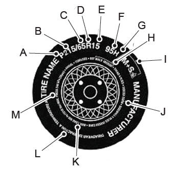
P215/65R15 95H is an example of a tire size, load index and speed rating. The definitions of these items are listed below. (Note that the tire size, load index and speed rating for your vehicle may be different from this example.)
P: Indicates a tire, designated by the Tire and Rim Association, that may be used for service on cars, sport utility vehicles, minivans and light trucks. Note: If your tire size does not begin with a letter this may mean it is designated by either the European Tire and Rim Technical Organization or the Japan Tire Manufacturing Association. 215: Indicates the nominal width of the tire in millimeters from sidewall edge to sidewall edge. In general, the larger the number, the wider the tire. 65: Indicates the aspect ratio which gives the tire's ratio of height to width. R: Indicates a radial type tire. 15: Indicates the wheel or rim diameter in inches. If you change your wheel size, you will have to purchase new tires to match the new wheel diameter. 95: Indicates the tire's load index. It is an index that relates to how much weight a tire can carry. You may find this information in your owner’s manual. If not, contact a local tire dealer.