Lincoln Corsair: Four-Wheel Drive Systems - 2.0L EcoBoost (177kW/240PS) – MI4/2.3L EcoBoost (199kW/270PS) / Description and Operation - Four-Wheel Drive Systems - System Operation and Component Description
System Operation
Principles of Operation
Power Transfer Unit (PTU) Operation
The PTU has four (4) modes of operation: Connected, Connecting, Disconnected, and Disconnecting. Each mode is commanded by the AWD module. The power transfer unit contains a reversible DC motor and two hall effect position sensors. The motor moves the shift fork which connects or disconnects the dog clutch collar. power transfer unit position sensor A monitors the position of the actuator cam. power transfer unit position sensor B monitors the position of the shift fork. Some power transfer unit models are equipped with an oil temperature sensor.
Connected Mode
Connected mode is the default mode for the power transfer unit. The AWD module will command Connected mode at the beginning of each key cycle. In connected mode, the fork and dog clutch collar are positioned towards the RH side of the power transfer unit and the dog clutch is engaged. The driveshaft will then rotate at an overdrive ratio compared to the front axle shafts. Torque will be available at the RDU .
Connecting Mode
To connect the power transfer unit, the two halves of the Dog clutch must be within 40 RPM of each other. The AWD module calculates the speed differential based on transmission OSS , RDU Driveshaft Speed, and power transfer unit gear ratio. The actuator motor will energize and rotate the gear reduction drive and the actuator cam against the shift fork. When the dog clutch teeth line up, the cam pushes the shift fork into position and the clutch engages. It can take approximately 100 - 150ms for the dog clutch to engage after the command is sent.
Disconnected Mode
The AWD module will command disconnected mode based on vehicle conditions. The purpose of the disconnected mode is to reduce drag losses from spinning the driveshaft when conditions indicate AWD will probably not be needed in the near future. In disconnected mode, the fork and dog clutch collar are positioned towards the LH or transmission side of the power transfer unit. The dog clutch is disengaged.
Disconnecting Mode
To allow disengagement of the RDU , no torque is routed through the power transfer unit, with the dog clutch being disconnected during this mode. Depending on vehicle operating conditions, the AWD module may keep the power transfer unit engaged for the remainder of the key cycle. The AWD module will send a duty cycle command to the power transfer unit actuator motor to disengage the dog clutch.
RDU Operation
Power distribution clutch motor for RDU:
The RDU System consists of an open type differential with an electronically controlled clutch pack that varies the torque applied to the rear axle shafts. The system has the capability to vary the amount of torque to the rear axles by controlling the clutch engagement pressure.
Economy Mode: When the RDU clutch pack is not engaged, the open differential allows the rear axle system to operated as a freewheeling axle, with no torque being transmitted from the RDU to either rear axle. In this mode the vehicle will operate as a 2WD system.
Connect Mode: When the AWD module determines that the AWD system function may be needed, the clutch pack is engaged to a “kiss point” by the actuator, spinning the rear axles up to speed. Once the wheel speed reaches a certain threshold, the power transfer unit will be connected (via the Torque mode), with torque provided to the RDU .
Torque Mode: When the vehicle is in torque mode, the RDU clutch motor will receive angular position commands to provide a requested amount of drive torque from the drive shaft to the rear axles. The RDU controls receive a torque request in Nm, which is converted into a motor angular position request value. These incoming torque requests are updated every 10ms by the AWD module.
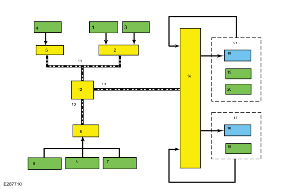
System Diagram
| Item | Description |
|---|---|
| 1 | Drive Mode |
| 2 | PCM |
| 3 | APP |
| 4 | Ignition Status |
| 5 | BCM |
| 6 | ABS module |
| 7 | Steering wheel angle data |
| 8 | Vehicle Acceleration |
| 9 | Wheel speed data |
| 10 | HS-CAN2 |
| 11 | HS-CAN1 |
| 12 | GWM |
| 13 | HS-CAN1 |
| 14 | AWD module |
| 15 | RDU speed / position sensor |
| 16 | RDU actuator motor |
| 17 | RDU |
| 18 | PTU (Power Transfer Unit) Actuator motor |
| 19 | PTU (Power Transfer Unit) Cam Position / speed sensor |
| 20 | PTU (Power Transfer Unit) temperature sensor (if equipped) |
| 21 | PTU (Power Transfer Unit) |
Spare Tire And Mismatched Tire Sizes
Major dissimilar tire sizes between the front and rear axles could cause the AWD system to stop functioning and default to FWD or damage the AWD system. It is recommended to reinstall a repaired or replaced road tire as soon as possible. When a mismatched or tire of the wrong size is fitted, an AWD OFF message may appear in the IPC . If this condition occurs, a DTC is set and an AWD OFF message is displayed on the message center. If there is an AWD malfunction service required message in the message center from using a spare or mismatched tire, this indicator should turn off after reinstalling a tire of the same size as the normal road tire, then cycling the ignition OFF and ON.
AWD Control And Fault Indicators
The AWD system consists of a Power Transfer Unit (PTU), driveshaft, front and rear halfshafts, AWD module, RDU with integral RDU coupling. The systems uses the AWD module for AWD control logic. Using inputs from various modules and systems, when the power transfer unit is engaged the AWD module sends a command to the RDU which controls the amount of torque applied to the to the rear wheels. AWD system faults are indicated by a driveline icon indicator in the IPC as well as the AWD malfunction service required message in the message center.
Heat Protection - Power Transfer Unit
During excessive use or when towing a trailer, the AWD system may implement a heat protection mode to protect the power transfer unit from damage. Using the input from power transfer unit temperature sensors (if equipped), the AWD module performs calculations to determine the demand for use of the heat protection mode. The AWD system then reduces the commanded torque being applied by the RDU to the rear axles, and/or disconnects the power transfer unit dog clutch. Once the maximum temperature limit is reached, AWD mode only is commanded and the AWD temporarily disabled or AWD OFF message is displayed in the IPC .
Heat Protection - Rear Drive Unit (RDU)
During aggressive on road driving, the AWD system may implement a heat protection mode to protect the RDU clutch from damage due to overheating. On variants not fitted with power transfer unit or RDU temperature sensors, the AWD module performs calculations to determine the need for the heat protection mode. If the AWD system detects an overheat condition, it enters a locked mode. If the heat in the RDU continues to rise once in the locked mode, the AWD module disables the torque commands to RDU . This condition may be indicated by an AWD Temporarily Disabled message in the message center. To resume normal operation, stop the vehicle in a safe location and turn the engine off for at least 10 minutes. After the engine is restarted and the AWD system has adequately cooled down, the AWD Temporarily Disabled message turns off and normal AWD operation returns. In the event the engine is turned off during the stop, the AWD Temporarily Disabled message turns off when the system cools. Normal AWD operation returns once the message center displays AWD Restored.
AWD Bar Code Identification
The RDU uses an actuator motor to control the RDU clutch, in turn applying drive torque to the rear axles. Due to response rate differences within the AWD hardware, the AWD module must be programmed with the response rate of the RDU coupling any time the AWD module or the RDU is replaced. This can be done by programming the RDU coupling bar code data into the AWD module. The AWD module uses this bar code information to match the clutch characteristics of the RDU coupling with the desired output torque. If the bar code information does not match the AWD module information, driveline damage or driveability concerns can occur. Therefore, if the RDU or AWD module needs to be replaced, the new unit needs to be configured using coupling bar code information.
RDU Coupling Configuration Bar Code Label Location
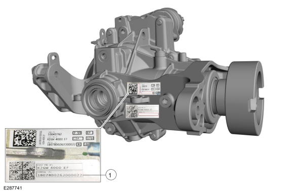
| Item | Description |
| 1 | RDU coupling bar code label (18078D026J000022) |
Component Description
Power Transfer Unit (PTU)
The
power transfer unit is a gearbox attached to the transmission, that
allows drive torque to be fed via a driveshaft to the rear axle via the
RDU . For more information on the power transfer unit, Refer to:
(307-07B Power Transfer Unit - 2.0L EcoBoost (177kW/240PS) – MI4)
Power Transfer Unit - Overview (Description and Operation).
RDU Actuator motor
The RDU clutch actuation motor is a brushless DC motor located on
the RDU . The motor is commanded by the AWD module and is used to
actuate the multi-plate clutch pack within the RDU which in turn engages
the rear drive axles. Refer to: (205-02 Rear Drive Axle/Differential)
 Description and Operation - Four-Wheel Drive Systems - Overview
NOTE:
The AWD system may be referred to as a 4WD
system or Active Torque Coupling (ATC) system in other service
information, owner literature, or messages located on the message
center...
 Diagnosis and Testing - Four-Wheel Drive Systems
Diagnostic Trouble Code (DTC) Chart
Diagnostics in this manual assume a certain skill level and knowledge of Ford-specific diagnostic practices.REFER to: Diagnostic Methods (100-00 General Information, Description and Operation)...
Other information:
Lincoln Corsair 2020-2024 Service Manual: Description and Operation - Airbag and Seatbelt Pretensioner Supplemental Restraint System (SRS) - System Operation and Component Description
System Operation System Diagram - Supplemental Restraint System (SRS) Item Description 1 RCM 2 HS-CAN2 3 Front Passenger Seat Position Sensor 4 HS-CAN1 5 HS-CAN3 6 Driver Seatbelt Buckle Sensor 7 Front Passenger Seatbelt Buckle Sensor 8 Passenger Front Impact Severity Sensor 9 Passenger Door Impact Sever..
Lincoln Corsair 2020-2024 Service Manual: General Procedures - Pyrotechnic Device Disposal
Disposal Disposal of Deployable Devices and Pyrotechnic Devices That Are Undeployed-Inoperative NOTE: All inoperative airbags, seatbelt pretensioners and inflatable seatbelt inflators have been placed on the Mandatory Return List. Treat all discolored or damaged airbags the same as any inoperative live airbag being returned. WARNING: Before beginning any service pro..
Categories
- Manuals Home
- 1st Generation Lincoln Corsair Owners Manual
- 1st Generation Lincoln Corsair Service Manual
- Auto-Start-Stop
- Refueling - Gasoline
- Memory Function
- New on site
- Most important about car
360 Degree Camera Cameras
Locating the Rear View Camera

The rear view camera is on the tailgate.
Locating the Front View Camera