Lincoln Corsair: Anti-Lock Brake System (ABS) and Stability Control / Description and Operation - Anti-Lock Brake System (ABS) and Stability Control - System Operation and Component Description
System Operation
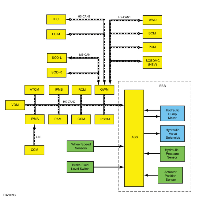
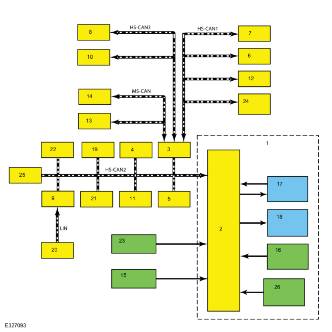
System Diagrams
| Item | Description |
|---|---|
| 1 | EBB assembly |
| 2 | ABS module |
| 3 | GWM |
| 4 | RCM |
| 5 | PSCM |
| 6 | BCM |
| 7 | AWD module |
| 8 | IPC |
| 9 | IPMA |
| 10 | FCIM |
| 11 | GSM |
| 12 | PCM |
| 13 | SODR |
| 14 | SODL |
| 15 | Brake fluid level switch |
| 16 | Hydraulic pressure sensor |
| 17 | Hydraulic pump motor |
| 18 | Hydraulic valve solenoids |
| 19 | IPMB |
| 20 | CCM |
| 21 | PAM |
| 22 | ATCM |
| 23 | Wheel speed sensors |
| 24 | SOBDMC ( HEV ) |
| 25 | VDM |
| 26 | Actuator position sensor |
Network Message Chart
Module Network Input Messages - ABS Module
| Broadcast Message | Originating Module | Message Purpose |
|---|---|---|
| Accelerator pedal position | PCM | This message is sent to the GWM and then to the ABS module. The ABS module uses accelerator pedal position information for correct operation of the ABS , traction control, ESC , RSC and the automatic release feature of the electronic parking brake system. |
| Adaptive cruise control braking deceleration | IPMA | This message is sent to the GWM and then to the ABS module. This message is used to request vehicle deceleration by the ABS module to maintain the distance gap set by the driver for the adaptive cruise control system. |
| Adaptive cruise control brake torque request | IPMA | This message is sent to the GWM and then to the ABS module. Informs the ABS module of the amount of braking required to maintain the distance gap set by the driver for the adaptive cruise control system. |
| Adaptive cruise control precharge request | IPMA | This message is sent to the GWM and then to the ABS module. This message is used to request precharging of the hydraulic brake system in preparation of a adaptive cruise control braking event. |
| Ambient air temperature | PCM | This message is sent to the GWM and then to the ABS module. Informs the ABS module of the current ambient air temperature. The ABS module uses this information for system diagnostics and DTC setting conditions. |
| AWD locking status | AWD control module | This message is sent to the GWM and then to the ABS module. Informs the ABS module of the current differential locked status; no fault, unspecified fault, differential failed open and differential failed closed. The ABS module requests differential unlocking during traction control, ESC and RSC operations. |
| AWD locking torque | AWD control module | This message is sent to the GWM and then to the ABS module. Informs the ABS module of the current amount of torque being applied to the differential. The ABS module requests differential unlocking during traction control, ESC and RSC operations. |
| Braking torque request | PCM | This message is sent to the GWM and then to the ABS module. Provides the amount of braking torque required for regenerative braking. |
| Brake pedal applied | PCM | This message is sent to the GWM and then to the ABS module. This message informs the ABS module the driver has pressed the brake pedal. This message is also used by the ABS module to check the brake pressure sensor located inside the HCU . |
| Braking request | IPMB | This message is sent to the GWM and then to the ABS module. This message is an adaptive cruise control braking request from the IPMB . |
| Cruise control status | PCM | This message is sent to the GWM and then to the ABS module. Informs the ABS module of the current cruise control system status; off, denied, standby denied, standby active que assist, active or undefined. |
| Clutch pedal data | PCM | This message is sent to the GWM and then to the ABS module. Informs the ABS module of the current clutch pedal data; pressed or not pressed, applied rate and percent of application. |
| Collision mitigation by braking deceleration | IPMA | This message is sent to the GWM and then to the ABS module. This message is used to request vehicle deceleration by the ABS module for the collision avoidance system. |
| Collision mitigation by braking precharge request | IPMA | This message is sent to the GWM and then to the ABS module. This message is sent to the GWM and then to the ABS module. This message is used to request precharging of the hydraulic brake system in preparation of a severe braking event. |
| Door ajar status | BCM | This message informs the ABS module of the current door ajar status. There is a separate message for each door and liftgate. The ABS module resets the parameters used for the ESC and RSC features when a door is opened. The message is also used for the EPB automatic release feature. |
| Driven wheel direction | PCM | This message is sent to the GWM and then to the ABS module. Provides the ABS module with the current direction of the driven wheels. This information is used for traction control and stability control purposes. |
| Driven wheel torque | PCM | This message is sent to the GWM and then to the ABS module. Provides the ABS module with the current torque output at the driven wheels. This information is used for traction control and stability control purposes. |
| Driven wheel regeneration torque | PCM | This message is sent to the GWM and then to the ABS module. Provides the ABS module with the current driven wheel braking torque output at the driven wheels. This information is used by the ABS module to support the regenerative braking system on the HEV . |
| Dynamic suspension data | VDM | Provides the ABS module with the current suspension data; whether the VDM has a fault and which selectable drive mode the suspension is currently operating under. The ABS module uses this information for stability control feature operation. |
| Engine disable status | PCM | This message informs the ABS module the engine is currently disabled or enabled due to the stop-start system. |
| Engine RPM | PCM | This message is sent to the GWM and then to the ABS module. Provides the ABS module with the current engine RPM . This information is used for traction control and stability control purposes. |
| Gear lever position | PCM | This message is sent to the GWM and then to the ABS module. Provides the ABS module with the current transmission gear lever position, this is used for the hill start assist system, the ESC and the RSC systems. The hill start assist system operates in forward and reverse gears. The ESC and RSC systems do not operate when the transmission is in REVERSE. The message is also used for the electronic parking brake automatic release feature. |
| Hill start assist request | IPC | This message is sent to the GWM and then to the ABS module. Provides the ABS module with the current, driver selected mode for the hill start assist system; off, auto or manual. |
| Ignition key type | BCM | This message is sent to the GWM and then to the ABS module. Informs the ABS module of the current ignition key type; standard or MyKey. The ABS modifies operating parameters if a restricted MyKey is used. |
| Ignition status | BCM | This message is sent to the GWM and then to the ABS module. Informs the ABS module of the current ignition status; off, accessory, run, start, unknown or invalid. |
| Odometer master value | IPC | This message is sent to the GWM and then to the ABS module. This message informs the ABS module of the current odometer value in kilometers. |
| Parking brake apply request | GSM | This message is a request for parking brake application from the GSM for the auto hold feature. |
| Parking brake apply request | PAM | This message is a request for parking brake application from the PAM for the active park assist feature. |
| Powertrain status | PCM | This message is sent to the GWM and then to the ABS module. Provides the ABS module with the current engine status; engine off, engine on or engine auto stopped. |
| RCM serial number | RCM | The ABS module stores the RCM serial number and verifies the serial number when the vehicle is started or the ignition is set to RUN or ACC. Over time, the ABS module learns the offset of the sensors inside the RCM . When a new serial number is found and the IVD Initialization procedure is carried out using a scan tool, the ABS module resets the offset number learned for ESC and RSC . |
| Restraint system impact event status | RCM | Provides the ABS module with the current SRS impact event status; normal, threshold 1 exceeded, threshold 2 exceeded or invalid. |
| Selectable drive mode request | ATCM | Provides the ABS module with the driver selected drive mode request. |
| Steering angle sensor data | PSCM | Several steering angle messages are sent to the ABS module from the PSCM . These messages include steering angle sensor status, steering wheel angle and steering wheel rotation count. The ABS module uses the steering angle sensor data for stability control feature operation. |
| Steering column torque | PSCM | Provides the ABS module with the current suspension height in millimeters. The ABS module uses this information for stability control feature operation. |
| Suspension height | VDM | Provides the ABS module with the current amount of torque being applied to the steering wheel by the driver. The ABS module uses this information for stability control feature operation. |
| Trailer sway configuration | IPC | This message is sent to the GWM and then to the ABS module. Informs the ABS module of the current vehicle trailer sway configuration. |
| Transmission in neutral | GSM | Informs the ABS module when the transmission has been placed in neutral mode. The ABS module modifies the operating parameters for stability control when the transmission is in neutral mode. |
| Transmission shift active | PCM | This message is sent to the GWM and then to the ABS module. Informs the ABS module when the transmission is shifting gears. This information is used for stability control purposes. |
| Transmission in reverse | PCM | This message is sent to the GWM and then to the ABS module. Informs the ABS module when the transmission is in REVERSE. The ESC and RSC systems do not operate when the transmission is in REVERSE. |
| Vehicle configuration data | BCM | This message is sent to the GWM and then to the ABS module. Provides the ABS module with the current optional and configured items such as tire size, axle ratio, manual or automatic transaxle, keyless entry and VIN . |
| Vehicle lateral acceleration data | RCM | Provides the ABS module with the current vehicle lateral acceleration information and whether or not the information is valid. |
| Vehicle longitudinal acceleration data | RCM | Provides the ABS module with the current vehicle longitudinal acceleration information and whether or not the information is valid. |
| Vehicle roll rate data | RCM | Provides the ABS module with the current vehicle roll rate information and whether or not the information is valid. |
| Vehicle speed data | PCM | This message is sent to the GWM and then to the ABS module. Provides the ABS module with the current vehicle speed. |
| Vehicle yaw data | RCM | Provides the ABS module with the current vehicle yaw information and whether or not the information is valid. |
Anti-Lock Brake System (ABS)
The ABS module continuously monitors brake pedal input, lateral vehicle motion and the rotational speed of each wheel. The PCM sends the brake pedal switch information to the GWM over the HS-CAN1 , the GWM sends the information to the ABS module over the HS-CAN2 . The RCM sends lateral acceleration sensor information directly to the ABS module over the HS-CAN2 . Wheel speed information is retrieved by the ABS module using 4 active wheel speed sensors. When the ABS module detects an impending wheel lock during a braking event, the ABS module modulates brake pressure to the appropriate brake calipers by opening and closing the appropriate solenoid valves inside the HCU while the hydraulic pump motor is activated. Once the affected wheel returns to the desired speed, the ABS module deactivates the hydraulic pump motor and returns the solenoid valves to their normal position.
The ABS module has 2 self-test options, one uses a diagnostic scan tool and the other is carried out when the ABS module is initialized (ignition on). During either self-test the ABS module carries out a preliminary electrical check of the system sensors and activates the hydraulic pump motor for approximately one-half second. During this time, a buzzing or humming noise may be heard and a vibration may be felt in the brake pedal; this is a normal condition. During the module initialized self-test, the pump motor check is carried out at approximately 10 km/h (6 mph). Any malfunction detected in the system causes the ABS module to set a DTC , disable the ABS function and send a message over the HS-CAN2 to the GWM . The GWM then sends the message to the IPC over the HS-CAN3 to illuminate the ABS warning indicator. Diagnostic Trouble Codes (DTCs) which disable the ABS do not disable the base hydraulic power-assist braking system.
Auto Hold
The auto hold feature is activated and deactivated through the use of the auto hold switch located on the FCIM . For the system to activate, the vehicle must not be moving, the driver safety belt must be buckled and the driver door must be closed.
The ABS module receives the driver safety belt buckle status from the RCM , driver door status from the BCM , while brake system pressure and the wheel speed are received from ABS sensors. This information allows the ABS module to determine if the vehicle is stopped. Once the previous conditions have been met the auto hold feature can be activated. When the switch is pressed, the FCIM receives a ground signal from the auto hold switch and sends an auto hold message to the GWM over the HS-CAN3 . The GWM relays the message to the ABS module over the HS-CAN2 .
The ABS module then sends a message to the instrument cluster through the GWM indicating the auto hold feature has been activated and the instrument cluster illuminates the auto hold indicator.
The auto hold indicator illuminates when the IPC receives a message from the ABS module through the GWM .
Once the auto hold feature is activated and the driver presses the brake pedal, the ABS module closes the isolation valves in the HCU to maintain the current brake system pressure at the wheel ends. The ABS module maintains the pressure until the driver presses the accelerator pedal, shifts the transmission into PARK or after a specific time limit has been reached. The ABS module engages the parking brake after 2-10 minutes, depending on the grade of incline the vehicle is currently stopped on, the steeper the grade, the shorter the time.
Electronic Brake Force Distribution (EBD)
On initial application of the brake pedal, full pressure is applied to the rear brakes. The ABS module then uses wheel speed sensor inputs to evaluate rear wheel slip. Once the rear wheel slip exceeds a predetermined threshold, the ABS module commands the HCU to close the appropriate isolation valves to hold the rear brake pressure constant while allowing the front brake pressure to build. This creates a balanced braking condition between the front and rear wheels. If the rear wheel slip continues and exceeds a second predetermined threshold, the ABS module commands the HCU to open the dump valves to decrease the rear brake pressure and allow the rear wheels to recover. A slight bump sensation may be felt in the brake pedal when EBD is active.
If the ABS is disabled due to a DTC being present in the ABS module, EBD continues to function unless the DTC is for wheel speed sensors or the HCU . When EBD is disabled, the ABS warning indicator, the red brake warning indicator and stability-traction control indicator (sliding car icon) illuminate.
Electronic Parking Brake (EPB) Features
The ABS module is the controlling ECU
for the electronic parking brake system and controls all parking brake
features such as automatic drive away release. For additional
information on the electronic parking brake system,
Refer to:
Parking Brake - System Operation and Component Description (206-05
Parking Brake and Actuation, Description and Operation).
Emergency Brake Assist (EBA)
The EBA feature helps drivers in a severe braking event, such as an emergency, by applying the maximum possible braking force.
If the brake pedal is pressed very suddenly, the ABS module increases the hydraulic pressure to all of the brakes until the threshold for ABS intervention is reached. This generates the maximum braking power for the available traction. The ABS module monitors inputs from the brake pedal switch and from the pressure sensor within the HCU to check for sudden actuation of the brakes. With the brake pedal pressed, the ABS module triggers emergency braking if the rate of increase of hydraulic pressure exceeds the predetermined limit.
If the brake pedal is pressed so hard the ABS becomes active on the front wheels, the ABS module increases the pressure to the rear wheels up to the ABS intervention threshold.
EBA operation continues until the driver releases the brake pedal sufficiently for the hydraulic pressure in the HCU to drop below a specific threshold value. This threshold is saved in the ABS module.
Hill Start Assist
When the vehicle is stopped on an incline greater than approximately a 3% grade, the ABS module holds the brake pressure for approximately 1.5 seconds while the driver transitions from the brake pedal to the accelerator pedal. This is accomplished by monitoring several HS-CAN messages and several sensors to determine if the vehicle is stopped and not parked, and if the vehicle is on an appropriate incline.
- The brake pedal message sent by the PCM and the wheel speed sensor inputs allow the ABS module to determine the vehicle has come to a complete stop.
- The transmission selector lever message sent by the PCM or GSM informs the ABS module the vehicle is not parked.
- The stability sensor messages sent by the RCM enable the ABS module to determine if the vehicle is on an appropriate incline.
Once the above conditions have been met, hill start assist automatically engages. Before the driver releases the brake pedal, the ABS module commands the HCU to close the isolation valves which maintains the current brake system pressure, preventing the vehicle from rolling down the incline. Once the driver presses the accelerator pedal and the engine RPM increases, the ABS module gradually releases the brake pressure to make sure the vehicle is neither rolling back nor driving off until there is sufficient driving torque to accelerate the vehicle forward (or backward if reversing up the incline).
Hydraulic Fade Compensation and Brake Fluid Support
Hydraulic fade compensation and brake fluid support provides a function to counteract faded brakes by supplying additional wheel brake pressure, if the maximum achievable vehicle deceleration is not reached, while the driver applies (very) high pedal force (driver brake request remains longer than a predetermined time). Brake fluid support provides a software function to increase fluid flow to the wheel end brakes in the event the brakes have faded to the extent the primary or secondary master cylinder circuits can no longer supply fluid to the brake system.
Supplemental Braking Assist
In addition to preventing wheel lock up during braking events, the ABS module also provides supplemental hydraulic brake assist through the use of the hydraulic pump motor and the HCU . This is done in the event of a severe braking event, to maintain the distance gap set by the adaptive cruise control system or to assist with collision avoidance.
The ABS module continually monitors CAN messages and sensor inputs. When the messages or sensors indicate a severe braking event is about to occur or is occurring, the ABS module activates the hydraulic pump motor in the HCU to assist with vehicle braking.
On vehicles equipped with adaptive cruise control, the CCM monitors the area forward of the vehicle.
When an object enters this area and closes the distance gap set by the driver, the CCM sends a deceleration request to the IPMA over a LIN . The IPMA then sends the message to the ABS module over the HS-CAN2 .
When the deceleration request message is received, the ABS module activates the hydraulic pump motor and solenoid valves in the HCU to slow the vehicle down to maintain the distance gap set by the driver. Once the distance gap set by the driver is achieved, the CCM stops sending the deceleration request message and the ABS module deactivates the hydraulic pump motor and solenoid valves in the HCU .
If the CCM determines the amount of braking provided by the ABS module is insufficient, the CCM sends a forward collision avoidance braking request message and warns the driver, both audibly and visually, through the use of the HUD . After receiving the braking request message, the ABS module waits for brake pedal input and, once received, applies maximum braking assist using the hydraulic pump motor and the HCU .
For additional information on the adaptive cruise control system,
Refer
to: Cruise Control - System Operation and Component Description
(419-03B Cruise Control - Vehicles With: Adaptive Cruise Control With
Lane Centering, Description and Operation).
For additional information on the collision avoidance system,
Refer
to: Collision Warning and Collision Avoidance System - System Operation
and Component Description (419-03C Collision Warning and Collision
Avoidance System, Description and Operation).
AdvanceTrac
The AdvanceTrac system is comprised of the ESC and traction control features.
Electronic Stability Control (ESC)
The ABS module continuously monitors the vehicle motion relative to the intended course. This is done by using sensors to compare the steering wheel sensor messages and the yaw rate sensor messages with the actual vehicle motion.
The PSCM sends the steering wheel angle information to the ABS module over the HS-CAN2 . The RCM sends yaw rate sensor and lateral accelerometer information to the ABS module also over the HS-CAN2 . If the ABS module determines from the inputs the vehicle is unable to travel in the intended direction, it modulates brake pressure to the appropriate brake calipers by opening and closing the appropriate solenoid valves inside the HCU while the hydraulic pump motor is activated. At the same time, the ABS module calculates how much engine torque reduction is required to help stabilize the vehicle and sends this torque reduction message to the GWM over the HS-CAN2 which relays the message to the PCM over the HS-CAN1 . The ABS module also sends a vehicle stability event message to the GWM over the HS-CAN2 which relays this message to the IPC over the HS-CAN3 . When the PCM receives the torque reduction message, it adjusts engine timing and decreases fuel injector pulses to reduce the engine torque to the requested level. When the IPC receives the vehicle stability event message, it flashes the stability-traction control indicator (sliding car icon).
Once the vehicle instability has been corrected, the ABS module returns the solenoid valves in the HCU to their normal position, deactivates the hydraulic pump motor and stops sending the ESC event and torque reduction messages. The PCM returns engine timing and fuel injectors to normal operation and the IPC extinguishes the stability-traction control indicator (sliding car icon).
ESC does not operate with the transmission in REVERSE. ESC is disabled if there is a wheel speed sensor, stability sensor or steering angle sensor DTC present in the ABS module. ESC is also disabled if there is a communication error between the ABS module and the PSCM , the ABS module and the PCM or the ABS module and the RCM . When ESC is disabled, the ABS module sends a message to the GWM over the HS-CAN2 . The GWM relays this message to the IPC over the HS-CAN3 to illuminate the stability-traction control OFF indicator (sliding car OFF icon).
Traction Control
The ABS module continuously monitors and compares the rotational speed of the drive wheels in relation to the non-driven wheels. When the drive wheels begin to spin faster than the non-driven wheels, the ABS module modulates brake pressure to the appropriate brake calipers by opening and closing the appropriate solenoid valves inside the HCU while the hydraulic pump motor is activated. At the same time, the ABS module calculates how much engine torque reduction is required to eliminate the wheel slip and sends this torque reduction message to the GWM over the HS-CAN2 which relays the message to the PCM over the HS-CAN1 . The ABS module also sends a traction event message to the GWM over the HS-CAN2 which relays this message to the IPC over the HS-CAN3 . When the PCM receives the torque reduction message, it adjusts engine timing and decreases fuel injector pulses to reduce the engine torque to the requested level. When the IPC receives the traction event message, it flashes the stability-traction control indicator (sliding car icon).
Once the driven wheel speed returns to the desired speed, the ABS module returns the solenoid valves in the HCU to their normal position, deactivates the hydraulic pump motor and stops sending the traction event and torque reduction messages. The PCM returns engine timing and fuel injectors to normal operation and the IPC extinguishes the stability-traction control indicator (sliding car icon). Once vehicle speed exceeds 100 km/h (62 mph), traction control is accomplished only through the PCM torque control.
The driver can disable the traction control feature by using the traction control switch or through the menu in the message center, refer to the Owner's Literature for instructions on disabling traction control. This is independent of the ABS and ESC , which cannot be disabled by the driver. Once disabled, the traction control feature remains disabled until the driver enables the system or the ignition is cycled from ON to OFF and back to ON.
When the traction control switch on the ATCM is pressed, a traction control status message is sent to the ABS module along the HS-CAN2 . The ABS module takes no further action in regards to traction control until the driver activates the function or until the ignition is cycled from OFF to ON.
Traction control is disabled automatically if there is a wheel speed sensor or solenoid valve DTC present in the ABS module. Traction control is also disabled if there is a communication error between the ABS module and the PCM . When traction control is disabled, the ABS module sends a message to the GWM over the HS-CAN2 . The GWM relays this message to the IPC over the HS-CAN3 to illuminate the stability-traction control indicator (sliding car icon).
Roll Stability Control (RSC)
The ABS module continuously monitors the vehicle motion relative to the intended course. This is done by using sensors to compare the steering wheel input, yaw rate sensor input, lateral accelerometer input and roll sensor input with the actual vehicle motion.
The PSCM sends the steering wheel angle information to the ABS module over the HS-CAN2 . The RCM sends yaw rate sensor, lateral accelerometer and roll rate sensor information to the ABS module also over the HS-CAN2 . If the ABS module determines from the inputs the vehicle is becoming unstable, the ABS module modulates brake pressure to the appropriate brake calipers by opening and closing the appropriate solenoid valves inside the HCU while the hydraulic pump motor is activated. At the same time, the ABS module calculates how much engine torque reduction is required to help stabilize the vehicle and sends this torque reduction message to the GWM over the HS-CAN2 which relays the message to the PCM over the HS-CAN1 . The ABS module also sends a vehicle stability event message to the GWM over the HS-CAN2 which relays this message to the IPC over the HS-CAN3 . When the PCM receives the torque reduction message, it adjusts engine timing and decreases fuel injector pulses to reduce the engine torque to the requested level. When the IPC receives the vehicle stability event message, it flashes the stability-traction control indicator (sliding car icon).
Once the vehicle instability has been corrected, the ABS module returns the solenoid valves in the HCU to their normal position, deactivates the hydraulic pump motor and stops sending the traction event and torque reduction messages. The PCM returns engine timing and fuel injectors to normal operation and the IPC extinguishes the stability-traction control indicator (sliding car icon).
RSC does not operate with the transmission in REVERSE. The ABS module automatically disables RSC if there are any wheel speed sensor, stability sensor or steering angle sensor Diagnostic Trouble Codes (DTCs) present in the ABS module. If there is a communication error between the ABS module and the PSCM or the ABS module and the RCM , RSC also is disabled. When RSC is disabled, the ABS module sends a message to the GWM over the HS-CAN2 . The GWM relays this message to the IPC over the HS-CAN3 to illuminate the stability-traction control indicator (sliding car icon).
Trailer Sway Control
Trailer sway is the undesirable yaw force a trailer can apply to the towing vehicle. Trailer sway control is a unique function of the stability control system that uses steering wheel angle information and yaw rate information to determine if a trailer sway event is taking place.
The PSCM sends the steering wheel angle information to the ABS module over the HS-CAN2 . The RCM sends yaw rate sensor and lateral accelerometer information to the ABS module also over the HS-CAN2 . If the ABS module determines from the inputs a trailer sway event is taking place, the ABS module modulates brake pressure to the appropriate brake calipers by opening and closing the appropriate solenoid valves inside the HCU while the hydraulic pump motor is activated. At the same time, the ABS module calculates how much engine torque reduction is required to eliminate the trailer sway and sends this torque reduction message to the GWM over the HS-CAN2 which relays the message to the PCM over the HS-CAN1 . The ABS module also sends a trailer sway event message to the GWM over the HS-CAN2 which relays this message to the IPC over the HS-CAN3 . When the PCM receives the torque reduction message, it adjusts engine timing and decreases fuel injector pulses to reduce the engine torque to the requested level. When the IPC receives the vehicle stability event message, it flashes the stability-traction control indicator (sliding car icon) and displays TRAILER SWAY REDUCE SPEED in the message center.
Once the trailer sway has been corrected, the ABS module returns the solenoid valves in the HCU to their normal position, deactivates the hydraulic pump motor and stops sending the traction event and torque reduction messages. The PCM returns engine timing and fuel injectors to normal operation and the IPC extinguishes the stability-traction control indicator (sliding car icon) and stops displaying the trailer sway message in the message center. Trailer sway control only activates when vehicle speed is greater than 65 km/h (40 mph). Any malfunction disabling RSC also disables trailer sway control.
The driver can disable and enable the trailer sway control feature using the message center and steering wheel controls. For additional information, refer to the Owner's Literature.
Selectable Drive Modes
The selectable drive mode system optimizes driveability and comfort as well as maximizing traction while operating on different types of terrain. The ATCM controls the drive mode selection. When a drive mode is selected, the ATCM sends the drive mode message to the ABS module over the HS-CAN2 . When the ABS module receives the message, it alters the intervention thresholds for ESC , RSC and traction control based on the selected mode. The ABS module also sends the drive mode message out to several other modules. The following modules receive the message and respond by altering their operation as follows:
- AWD module: automatically engages and disengages specific 4WD modes and raises or lowers torque output based on the selected mode.
- PCM : adjusts throttle response and gear changes to enhance powertrain response based on the selected mode.
- PSCM : adjusts steering effort and feel based on the selected mode.
- VDM : adjusts suspension height based on the selected mode.
The following drive modes are available:
- Conserve: For efficient and responsible driving. This mode helps deliver maximum fuel efficiency and increases driving range.
- Deep Conditions: For crossing deformable deep, rutted terrain such as mud, deep sand or deep snow. Do not use on dry, hard surfaced roads. If equipped, the air suspension is raised approximately 30 mm (1.2 in.) at low speeds for improved ground clearance.
- Deep Sand: For deep, soft and dry sand.
- Excite: For aggressive on-road driving. This mode increases throttle response, provides a sportier exhaust sound and steering feel, along with quicker shifting. The transmission holds gears longer, helping the vehicle accelerate faster when shifting gears. If equipped, the air suspension is lowered approximately 15 mm (0.6 in.) at for improved aerodynamics.
- Normal: For everyday driving. This mode is a perfect balance of excitement, comfort and convenience.
- Slippery: For less than ideal road conditions, such as snow or ice covered roads. Slippery mode lowers throttle response and optimizes shifting for slippery surfaces.
Drive mode changes are not available when the ignition is off. If a mode is unavailable, the system defaults to Normal mode.
MyKey® Interaction
Through the MyKey® feature, traction control can be configured to be always on or to allow the driver to select traction control on or off. When MyKey® traction control feature is configured to be always on and a MyKey® restricted key is in use, the IPC ignores any requests made by the driver to disable traction control and does not send any traction control disable messages to the ABS module. Refer to the Owner's Literature for additional information on the MyKey® feature and settings.
Stability-Traction Control Indicator (Sliding Car Icon)
One or both of the stability-traction control indicators may illuminate as a result of momentary sensor disturbances due to environmental or driving conditions (including severe vehicle maneuvers or extreme off road usage). Once Illuminated, the indicator remains illuminated until the environmental or driving condition is no longer present and the ignition is cycled from ON to OFF and then back to ON again. If there are no other customer concerns, symptoms, indicators or Diagnostic Trouble Codes (DTCs), the stability-traction control indicator may have been illuminated due to these environmental or driving conditions.
Refer to: Instrument Panel Cluster (IPC) - System Operation and
Component Description (413-01 Instrumentation, Message Center and
Warning Chimes, Description and Operation).
Stability-Traction Control Disabled Indicator (Sliding Car OFF Icon)
Refer to: Instrument Panel Cluster (IPC) - System Operation and
Component Description (413-01 Instrumentation, Message Center and
Warning Chimes, Description and Operation).
Component Description
Auto Hold Switch
The auto hold switch is a momentary contact, push button switch and is part of the FCIM .
Brake Fluid Level Switch
The brake fluid level switch is mounted on the brake fluid reservoir and is hardwired to the ABS module. The ABS module provides a reference voltage to the brake fluid level switch and the switch is grounded through the ABS module along a separate ground circuit.
Drive Mode Switch
The drive mode switch is a multi-position, rotating switch and is part of the ATCM .
Electric Brake Booster (EBB) Assembly
The EBB is serviced as a single assembly and should NOT be disassembled. The EBB assembly contains the ABS module, solenoid valves, pressure sensor and hydraulic pump motor; the EBB also takes the place of the brake master cylinder and the vacuum booster.
The ABS module is serviced as an assembly with the EBB . The ABS
module is the ECU for the ABS and stability control systems. The module
monitors all sensor inputs and all CAN messages relating to ABS and
stability control, then directly controls the solenoid valves and the
hydraulic pump motor in the EBB . When a new EBB assembly is installed,
the ABS
module must be programmed with the current vehicle configuration
information. For additional information on module programming,
Refer
to: Module Configuration - System Operation and Component Description
(418-01 Module Configuration, Description and Operation).
When an ABS or stability control fault has been corrected or a new component has been installed, the ABS module must be calibrated using the ABS Calibration routine found on the diagnostic scan tool. ABS Calibration is required for the stability control sensors to learn the zero-position of the vehicle which means the vehicle must be on a level surface and not moving.
Stability Control Sensors
The stability control sensors for the vehicle dynamic system consist of the yaw rate sensor, lateral accelerometer, longitudinal accelerometer and roll rate sensor. The sensors are housed in the RCM which sends sensor information to the ABS module over a private HS-CAN . If any of the sensors are defective, a new RCM must be installed.
- The yaw rate sensor measures the yaw angle which is the difference between the direction the vehicle is pointing when cornering and the direction the vehicle is actually moving.
- The longitudinal accelerometer measures the acceleration and deceleration of the vehicle as it moves forward and backward.
- The lateral accelerometer measures the force created when a vehicle corners that tends to push a vehicle sideways.
- The roll rate sensor measures the rate of rotation of the vehicle along the centerline of the vehicle from front to back.
Lateral acceleration has 2 forms. The first is the centrifugal acceleration that is generated when the vehicle travels around in a circle. The second is the acceleration due to gravity. On level ground there is no lateral acceleration due to gravity. However, if the vehicle is parked sideways on a bank or incline, the sensor measures some lateral acceleration due to gravity, even though the vehicle is not moving.
Traction Control Switch
The traction control switch is a single-pole, momentary-contact button and is part of the ATCM .
Wheel Speed Sensor (WSS)
On vehicles not equipped with features requiring low speed active braking, such as active park assist, all 4 wheel speed sensors are active (magneto resistive) sensors operating on the Hall-effect principle to generate a square wave signal proportional to the rotational speed of the wheel. Because these are active sensors, receiving voltage from the ABS module and then sending a varying voltage back to the ABS module, they are able to detect much lower rotational speeds than passive (magnetic inductive) sensors. Each wheel speed sensor is connected to the ABS module by 2 circuits. One circuit provides voltage for sensor operation and the other circuit provides sensor input to the ABS module.
On vehicles equipped with features requiring low speed active braking, such as active park assist, both rear wheel speed sensors are active, bi-directional sensors. Each of the 2 sensors contain 2 sensing elements mounted side-by-side. Because the 2 sensing elements are mounted next to each other the 2 voltage signals are slightly out of phase, which causes one element to generate a voltage signal before the other element. This allows the ABS module to not only determine wheel speed, but also wheel direction for low speed active braking features.
Wheel Speed Sensor Encoders
The wheel speed sensor encoders are magnetized rings used to create a Hall-effect switch when combined with the wheel speed sensor.
On 2WD vehicles, all 4 wheel speed sensor encoders are integrated into the wheel bearing and hub assemblies and are serviced with the assemblies.
On AWD vehicles, the rear wheel speed sensor encoders are pressed onto the rear axle shaft and are serviced with the axle shaft. While the front wheel speed sensor encoders are integrated into the wheel bearing and hub assemblies and are serviced with the assemblies.

 Diagnosis and Testing - Anti-Lock Brake System (ABS) and Stability Control
Diagnostic Trouble Code (DTC) Chart
Diagnostics in this manual assume a certain skill level and knowledge of Ford-specific diagnostic practices. REFER to: Diagnostic Methods (100-00 General Information, Description and Operation)...
Other information:
Lincoln Corsair 2020-2024 Service Manual: Removal and Installation - Steering Column Shaft
Removal NOTE: Removal steps in this procedure may contain installation details. NOTICE: Do not allow the steering wheel to rotate while the steering column shaft is disconnected or damage to the clockspring may result. If there is evidence that the shaft has rotated, remove and recenter the clockspring...
Lincoln Corsair 2020-2024 Owners Manual: Locking and Unlocking the Doors Using Keyless Entry
Unlocking the Doors Enter the factory-set five-digit code or your personal code. You must press each number within five seconds of each other. The interior lamps illuminate. Note: All doors unlock if you disable the two-stage unlocking feature. To disable the two-stage unlocking feature: Switch the ignition on using an admin key...
Categories
- Manuals Home
- 1st Generation Lincoln Corsair Owners Manual
- 1st Generation Lincoln Corsair Service Manual
- Child Safety Locks
- Exterior Mirrors
- Normal Scheduled Maintenance
- New on site
- Most important about car
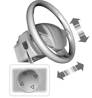
Adjusting the Steering Wheel - Vehicles With: Power Adjustable Steering Column
WARNING: Do not adjust the steering wheel when your vehicle is moving.
Note: Make sure that you are sitting in the correct position.